GASOLINE ENGINES BRAVO MODELS
Page 110 of 116
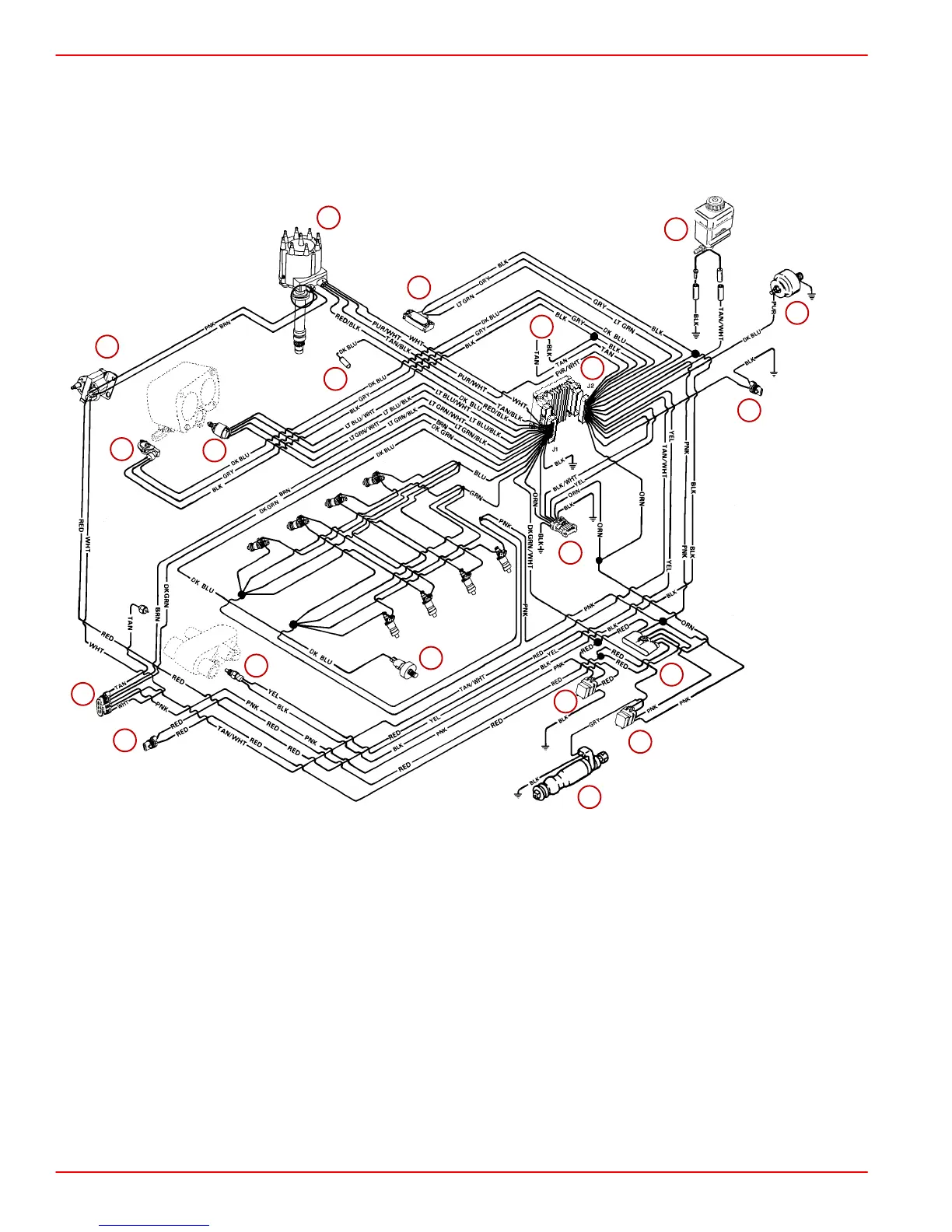
MCM 454 & 502 Mag MPI Models - Fuel and Ignition System Harness
NOTE: All BLACK wires with a ground symbol are interconnected within the EFI system har-
ness.
NOTE: Component position and orientation shown is arranged for visual clarity and ease
of circuit identification.
75994
2
BLK = BLACK
BLU = BLUE
BRN = BROWN
GRY = GRAY
GRN = GREEN
ORN = ORANGE
PNK = PINK
PUR = PURPLE
RED = RED
TAN = TAN
WHT = WHITE
YEL = YELLOW
LIT = LIGHT
DRK = DARK
1
2
3
4
5
6
8
9
10
11
12
13
14
15
16
17
18
7
19
19
1-Fuel Pump
2-Distributor
3-Coil
4-Data Link Connector (DLC)
5-Manifold Absolute Pressure (MAP) Sensor
6-Knock Sensor
7-Idle Air Control (IAC)
8-Throttle Position (TP) Sensor
9-Engine Coolant Temperature (ECT) Sensor
10 - Electronic Control Module (ECM)
11 - Fuel Pump Relay
12 - Ignition/System Relay
13 - Harness Connector To Starting/Charging Har-
ness
14 - Positive (+) Power Wire To Engine Circuit
Breaker
15 - Fuse (10 Amp) ECM / Injector / Ignition / Knock
Module
Fuse (15 Amp) Fuel Pump
Fuse (15 Amp) ECM/DLC/Battery
16 - Gear Lube Monitor Bottle
17 - Oil Pressure -Audio Warning Switch
18 - Load Anticipation Circuit
19 - Wires Not Used