GASOLINE ENGINES BRAVO MODELS
Page 32 of 116
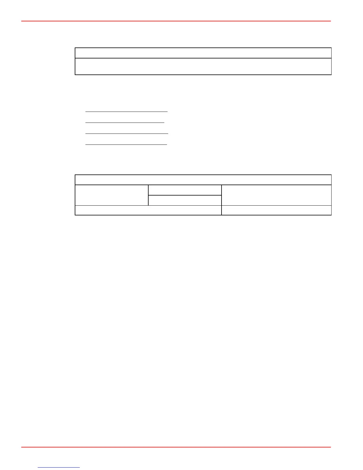
Transom Cutout
NOTICE to INSTALLER
Before Starting Installation Read “General Information” and “Installation Require-
ments” Sections Completely.
IMPORTANT: The following instructions will provide a sterndrive unit mounting loca-
tion that is suitable for most boats. Best mounting location for a particular boat, how-
ever, can be determined only by testing.
1. Below 25 m.p.h. (40 km/h):
Subtract 1/2 in. (13mm) from “X” Dimension shown.
2. Heavy Duty Applications:
Subtract 1 in. (25mm) from “X” Dimension shown.
3. Above 25 m.p.h. (40 km/h):
Use “X” Dimension shown.
4. Above 50 m.p.h. (80 km/h):
The “X” Dimension can be increased to improve perform-
ance in some applications, but pulling power (for skiing) will decrease. During testing,
the “X” Dimension should be increased 1/2 in. (13mm) at a time until desired perform-
ance is achieved but in no case should it ever be increased by more than:
Maximum Increase In “X” Dimension
One
Bravo
Two
3 in. (76 mm) maximum
Bravo Three 1 in. (25 mm) maximum
In ALL sterndrive applications, extreme care should be taken when raising sterndrive unit
to ensure that water supply does not become aerated. Use clear water inlet hose to monitor
incoming water and monitor engine temperature gauge to ensure engine does not overheat.
In applications where cooling water to the engine is supplied by a through the hull
or through the transom fitting, the sterndrive height will not cause cooling water aeration.
IMPORTANT: Damage to Mercury MerCruiser products caused by too high of an
installed height will not be covered by Mercury MerCruiser warranty.