GASOLINE ENGINES BRAVO MODELS
Page 37 of 116
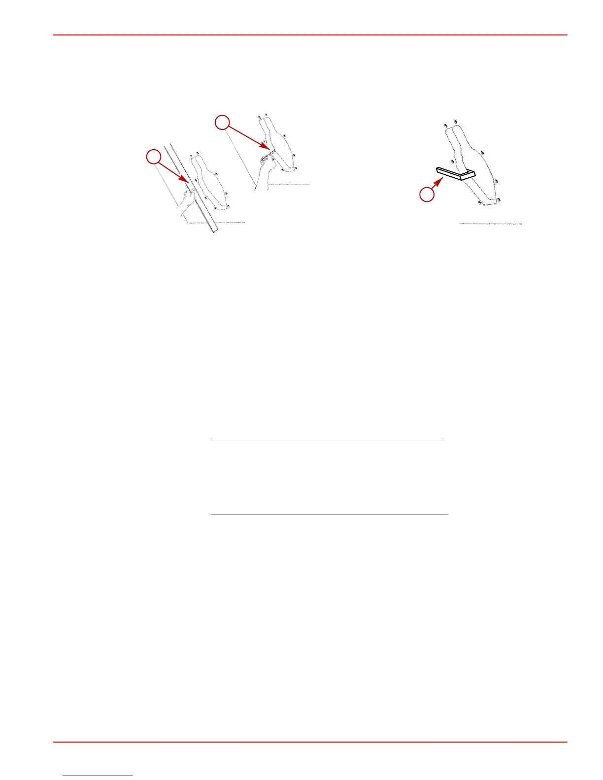
Checking Transom Thickness
Ensure transom surface thickness and flatness conform to minimums specified in “Installa-
tion Requirements” listed previously.
70004
a
b
75479
c
a-Measuring Thickness
b-Measuring Flatness
c-Suitable Mandrel To Check For Uniform Transom Thickness
NOTE: Transom must be between 2 in. (51 mm) and 2-1/4 in. (57 mm) a distance of
8” (203 mm) to either side of the vertical centerline.
Installing Transom Assembly
Installing Gimbal Housing
1. Carefully remove transom assembly from shipping carton.
2. Remove and read all tags which are attached to transom assembly.
IMPORTANT: When installing through the transom exhaust
, it is recommended that
the exhaust bellows on the transom assembly be removed. This is necessary to avoid
creating a vacuum at the exhaust outlet in the propeller at higher boat speeds. This
vacuum could degrade propeller performance on some boats.
3. If required, remove and discard clamps and bellows from gimbal housing.
IMPORTANT: When installing through the propeller exhaust
:
• With Bravo One and Bravo Two Sterndrives an exhaust tube MAY BE INSTALLED
for a slight increase in performance.
• With most Bravo Three Sterndrive Models an exhaust tube MAY BE INSTALLED
for a slight increase in performance. On the following Bravo Three Models, the
exhaust bellows must be removed and an exhaust tube MUST BE INSTALLED:
w MCM 7.4L MPI
w MCM 454 Mag MPI
w MCM 502 Mag MPI