GASOLINE ENGINES BRAVO MODELS
Page 19 of 116
INSTALLATION
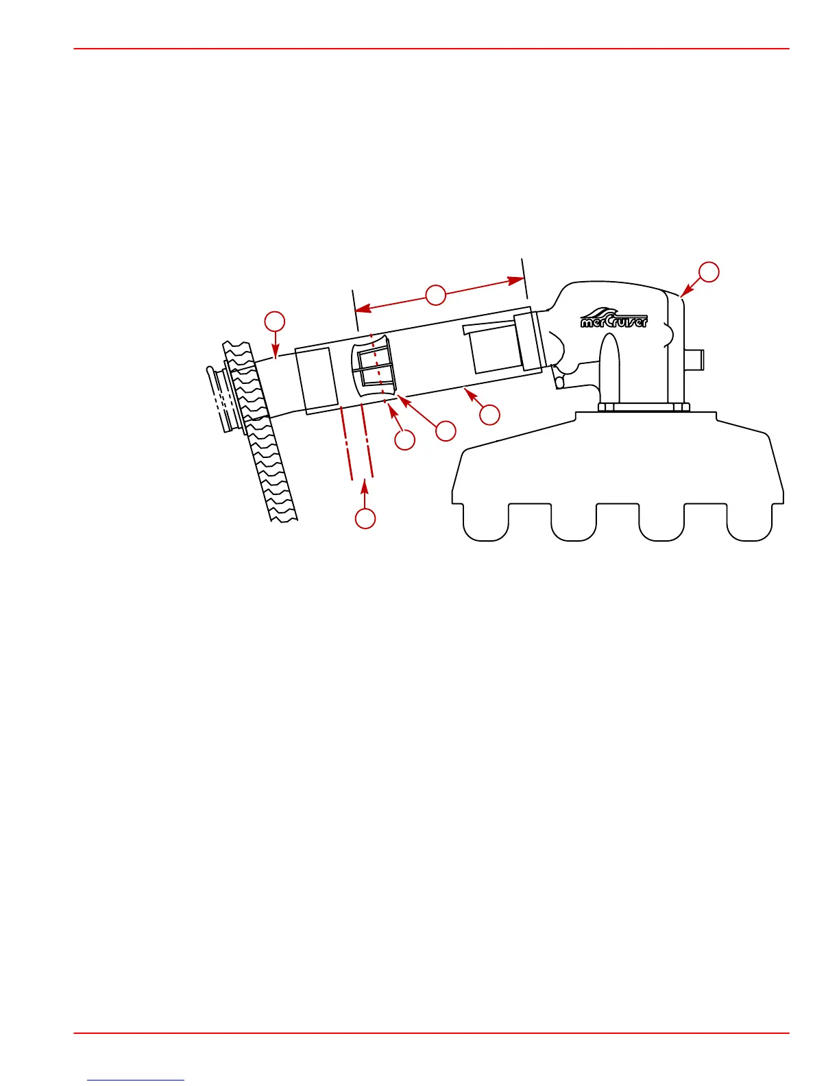
The resonator is installed in exhaust hose with open end toward exhaust elbow. Resonator
is positioned so that inside flat surface is approximately 17 in. (432 mm) from front edge
of exhaust hose, but no closer than 2 in. (51 mm) to exhaust outlet on sterndrive. The
17 in. (432 mm) dimension can be reduced, if necessary, to a minimum of no less than
13 in. (330 mm).
A clamp is then installed and tightened around the hose so that it clamps around center of
resonator. This position is 1 in. (25 mm) less than the position of the resonator as discussed
in the previous paragraph.
75203
a
e
b
c
d
f
g
Through The Transom Exhaust With Resonator
a-Exhaust Resonator
b-Exhaust Hose
c-Dimension To Inside Flat Surface Of Resonator Approximately 17 in. (432 mm),
But No Less Than 13 in. (330 mm)
d-No Less Than 2 in. (51 mm) Between Fitting And Resonator
e-Clamp Position - Around Center Of Resonator
f-Exhaust Fitting
g-Exhaust Elbow
454 AND 502 MAG BRAVO MODEL EXHAUST RECOMMENDATION
IMPORTANT: To get maximum performance from Magnum Bravo Models, through the
transom or hull exhaust is required.
NOTE: If noise regulations do not allow the use of through the transom or hull exhaust, an
exhaust pipe kit (Quicksilver Part Number 44266A6) must be installed for through the prop
exhaust. This kit also contains an exhaust tube that is used in place of the exhaust bellows.
IMPORTANT: It is recommended that the exhaust bellows on the transom assembly
be removed. This is necessary to avoid creating a vacuum at the exhaust outlet in the
propeller at higher boat speeds. This vacuum could degrade propeller performance
on some boats.