GASOLINE ENGINES BRAVO MODELS
Page 68 of 116
4. Do not strap or clamp the control cables to any other cables or rigid structure within
3 ft. (915 mm)of the control box.
5. Be sure the cable is not allowed to be kinked.
6. Make sure there is proper clearance for cable movement when the control box is
installed in the side panel. The cables must have room to move up and down when the
control handle is shifted into either forward or reverse.
7. Check to make sure that the engine was not set down on the intermediate shift cable
during installation, as this will crush the inner cable tubing and cause improper and / or
stiff shifting.
8. DO NOT fasten the shift cable with straps or clamps to any other cable within 5 ft.
(1.5 m) of the shift plate.
9. DO NOT fasten the shift cable to the transom with any type of plastic clips or fasteners
within 5 ft. (1.5 m) of the shift plate.
10. DO NOT overtighten the throttle or shift cable attaching nuts at the engine end. Barrel
and cable end must be free to rotate on the mounting stud.
NOTE: Lubricate attaching points with motor oil.
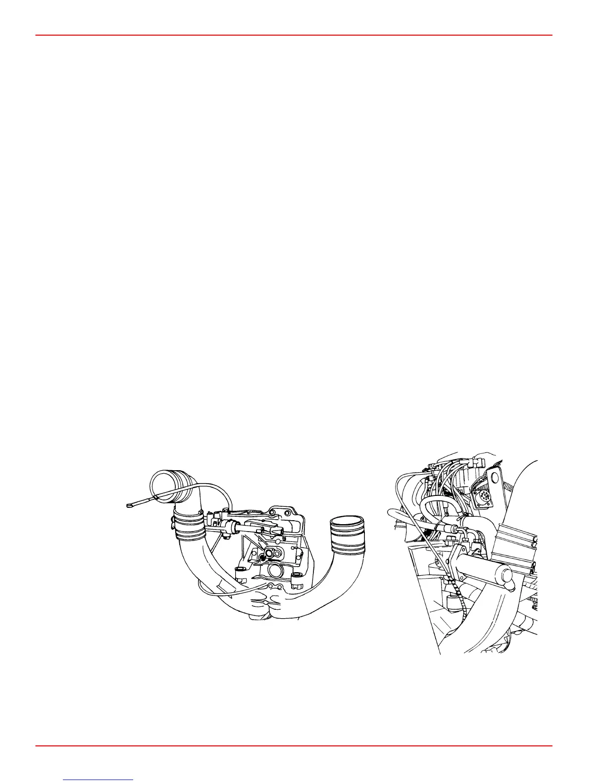
11. Check the intermediate shift cable routing from the transom assembly to the shift plate
as follows:
a. Route the cable through the transom above the exhaust pipe and turn it toward the
starboard side of the boat between the exhaust pipe and the engine flywheel hous-
ing.
b. Then route the cable under the starboard rear engine mount and turn it toward the
transom.
c. Then route the cable up behind the power steering valve and loop it over to the shift
plate on the engine and connect it to the anchor points on the shift plate.
Following this routing will prevent the engine coupler from damaging the cable.
75767
74904
V6 and V8 (except 7.4L) Models 7.4L Mag MPI Models
NOTE: A final check of the adjustments should be made with the boat in the water and
engine running. If this cannot be done or is not done at your manufacturing facility,
arrangement should be made with the dealer to do this as part of the pre-delivery inspection.
 Loading...