MI 3290 Earth Analyser Appendix C –Functionality and placing of test probes
147
Appendix C – Functionality and placing of test
probes
For a standard earthing resistance two test probes (voltage and current) are used. Because of
the voltage funnel it is important that the test electrodes are placed correctly. More information
about principles described in this document can be found in the handbook: Grounding, bonding,
and shielding for electronic equipment and facilities.
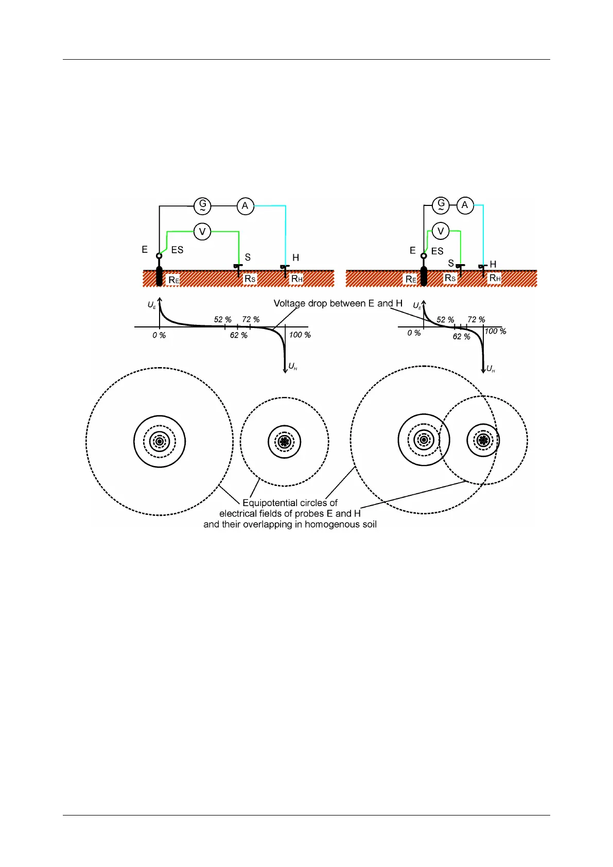
Figure C.1: Placement of probes
Probe E is connected to the earthing electrode (rod).
Probe H serves to close the measuring loop. The voltage between probe S and E is the voltage
drop on the measured resistance. Correct placing of probes is essential. If the S probe is placed
too close to the earthing system, then too small resistance will be measured (only a part of the
voltage funnel would be seen).
If the S probe is placed too close to the H probe the earthing resistance of voltage funnel of the
H probe would disturb the result.
It is important that the size of the earthing system is known, for the correct test probe placement.
Parameter a represents the maximum dimension of the earthing electrode (or a system of
electrodes) and can be defined acc. to Figure C.2.