MI 3290 Earth Analyser Tests and Measurements
86
Notes:
Consider displayed warnings when starting the measurement!
High noise currents and voltages in earth could influence the measurement results. The
tester displays the “noise” warning in this case.
When measuring at high frequencies use the guard terminal and shielded cable (H).
Notes (Probes and Flex):
High impedance of S and H probes could influence the measurement results. In this
case, “Rp” and “Rc” warnings are displayed.
Probes must be placed at a sufficient distance from the measured object.
When using only one, two or three flex clamps, always connect one clamp to F1
terminal (synchronization port).
Make sure that the arrow marked on the clamp coupling points toward the correct
orientation for correct phase measurement.
Make sure that the number of turns is correctly entered in the test parameters window
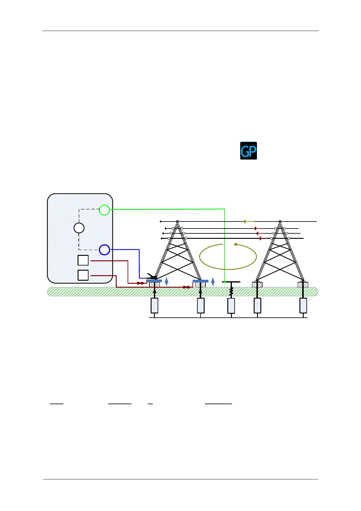
11.2.8 Passive (Flex Clamps) Measurement
The passive measuring method is using the “Inductive current” or grounding wire current I
gw
flowing in the earthing system to determine the selected earth resistances of individual
earthing points. The measurement method is using only one auxiliary potential probe (S).
E a r t h
S
E
MI 3290 Earth Analyser
Ze1/1
Rp
V
S - probe
tower 1
Ze2/1
F2
F1
Flex clamp
tower 2
Ze2/2
Ze1/2
L1
L2
L3
i1
i2
i3
nex tower
overhead grounding wire
Igw
If1
If2
Igw
Figure 11.36: Passive (Flex Clamps) example
During the measurement a “inductive current” - I
gw
is flowing into the earth through Z
sel1/1
,
Z
sel2/1
, Z
sel1/2
and Z
sel2/2
. A higher noise current improves the overall measuring result. The
voltage drop is measured by auxiliary potential probe (S). The selective currents I
f1-4
is
measured through the earthing electrode Z
sel1-4/1
selected by the user. The selected earth
impedance Z
sel1-4/1
is determined from the voltage/current (external current clamp – I
f1-4
) ratio.
Total earth impedance is measured:
where: