MI 3290 Earth Analyser Tests and Measurements
84
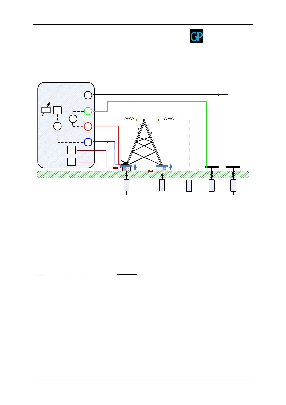
11.2.7 Selective (Flex Clamps 1 - 4) Measurement
This measurement is applicable for measuring selective earth resistances of individual
earthing points of an earthing system - Typical example is a pillar of the power line. The
connection to remote earthing (OHGW) rods does not need to be disconnected during the
measurement.
4-pole wiring is used for this measurement.
E a r t h
H
S
ES
E
MI 3290 Earth Analyser
Rp
G
V
A
S - probe
H - auxiliary
earth rod
Rc
Zsel2
F2
F1
Flex clamp
fset
tower
nex tower
overhead grounding wire
LGW
nex tower
RGW
LGW
Ie
Zsel1
If1 If2
Ih
Igw
Igw
Figure 11.31: Selective (Flex Clamps 1-4) example
During the measurement a sinusoidal current I
h
is injected into the earth through an auxiliary
probe (H). The impedance of the auxiliary probe (H) should be as low as possible in order to
inject a high test current. The impedance R
c
can be decreased by using more probes in
parallel. A higher injected current improves the immunity against spurious earth currents. The
ground potential rise is measured by auxiliary potential probes (S) and (ES).
The selective currents If1-4 are measured through the earthing electrodes Zsel1-4 selected
by the user. The selected earth impedance Zsel1-4 is determined from the voltage/current
(external current clamp – If1-4) ratio.
The total earth impedance is measured:
where:
Z
tot
..................................... Total selected earth impedance
Z
sel1-4
................................. Selective earth impedance
R
c
...................................... Impedance of auxiliary current probe (H)
R
p
..................................... Impedance of auxiliary potential probe (S)
I
h
........................................ Injected test current
I
e
........................................ Measured test current
I
f1-4
..................................... Measured current with Flex clamp
U
S-ES
.................................. Test voltage between S and ES terminal
f
set
..................................... Test frequency
Refer to Appendix C – Functionality and placing of test probes for more information how
to place the earth auxiliary current (H) and potential probe (S).