MI 3290 Earth Analyser Tests and Measurements
99
11.6 AC Impedance [Z]
An impedance vector consists of a real part (resistance, R) and an imaginary part (reactance,
X) as shown in Figure 11.60.
Imaginary Axis
R
Real Axis
L
C
R
φ
Z
(
R
,
X
)
where:
Z
.......Impedance
R .......Real part of impedance (resistance)
jX ......Imaginary part of impedance (reactance)
φ ......Phase angle
Figure 11.60: A graphical representation of the complex impedance plane
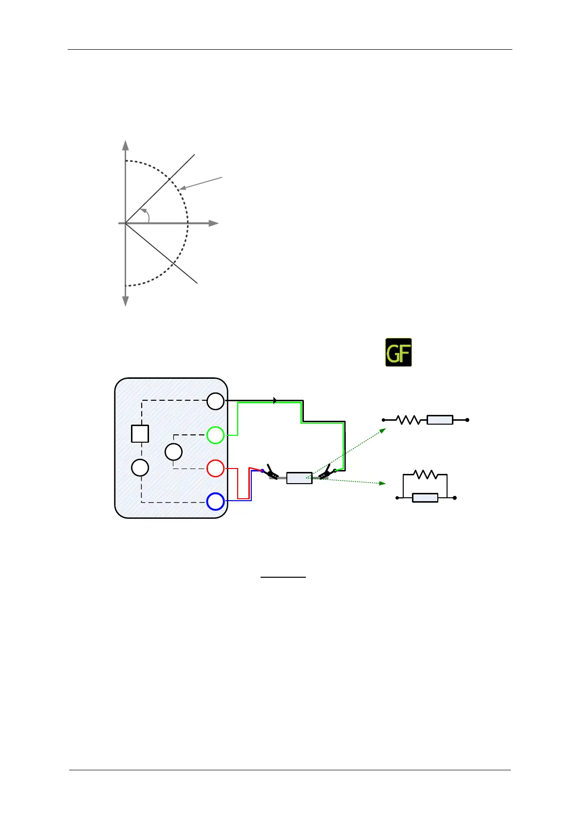
11.6.1 Impedance Meter Measurement
C1
P1
P2
C2
MI 3290 Earth Analyser
G
Vac
Aac
Zx
4 wire (Kelvin)
Iac
R
R
jX
jX
Series
Parallel
Figure 11.61: Impedance Meter example 4-wires
In the example following impedance is measured:
where:
Z
....................................... Impedance
I
ac
...................................... Injected AC test current between C1 and C2 terminals
U
ac
.................................... Measured AC voltage between P1 and P2 terminals (4-wires)
SER/PAR Model parameter:
Series – Activates the series equivalent circuit model
Parallel – Activates the parallel equivalent circuit model