MI 3290 Earth Analyser Tests and Measurements
75
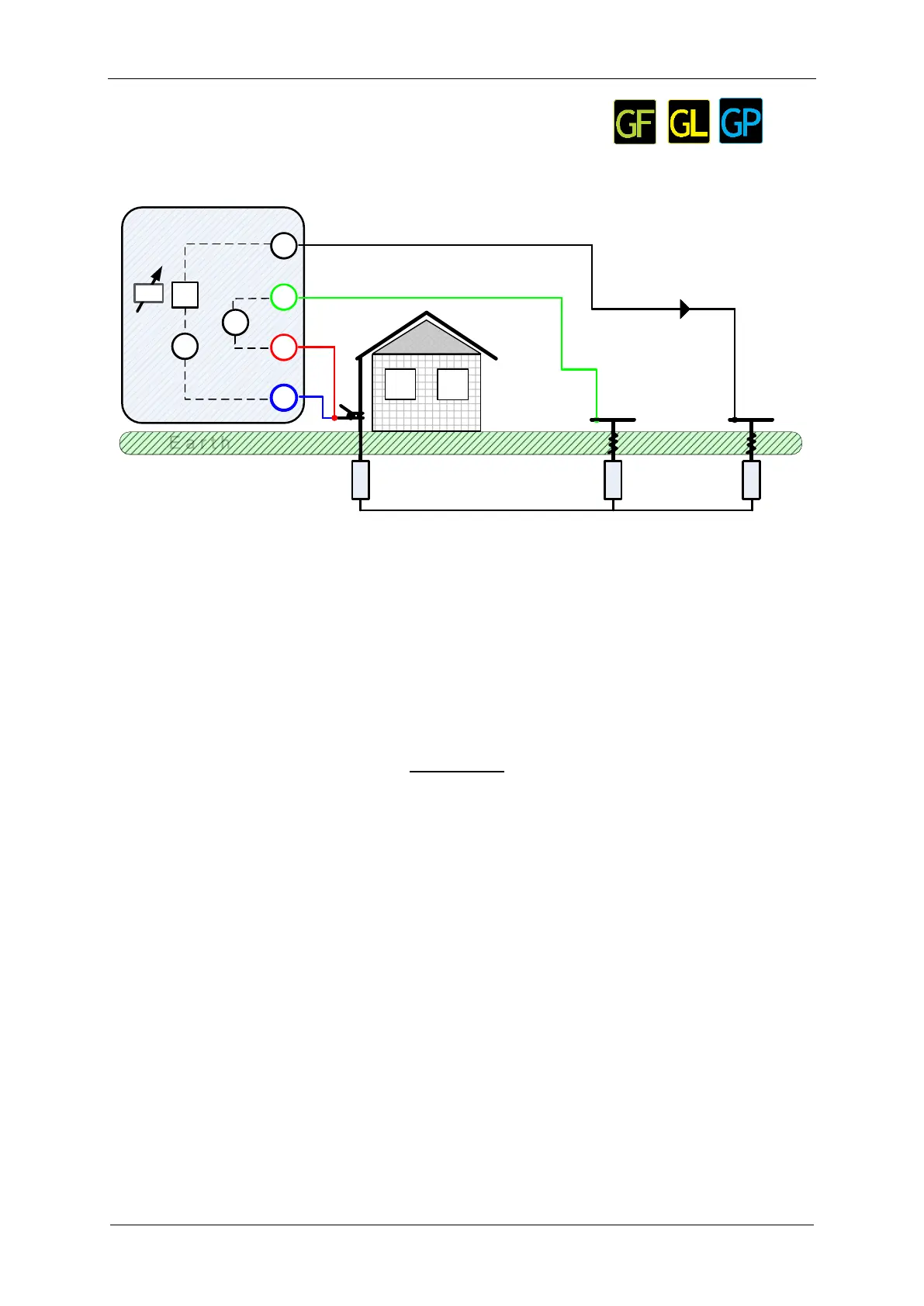
11.2.3 4 – pole Measurement
The advantage for using of four-pole test is that the leads and contact resistances between
measuring terminal E and tested item do not influence the measurement.
E a r t h
H
S
ES
E
MI 3290 Earth Analyser
G
V
A
Ie
Rp
S - probe
H - auxiliary
current probe
Rc
Re
E a r t h
H
S
ES
E
G
V
A
Ie
Rp
Rc
Ze
fset
Figure 11.16: 4 – pole example
During the measurement a sinusoidal current I
e
is injected into the earth through an auxiliary
current probe (H). The impedance of the auxiliary probe (H) should be as low as possible in
order to inject a high test current. The impedance R
c
can be decreased by using more probes
in parallel. A higher injected current improves the immunity against spurious earth currents.
The differential voltage drop is measured by auxiliary potential probe (S) and (ES) terminal.
The earth impedance Ze is determined from the voltage/current ratio.
In the example following earth impedance is measured:
where:
Z
e
...................................... Earth impedance
R
e
..................................... Earth resistance (excluding reactance)
R
c
...................................... Impedance of auxiliary current probe (H)
R
p
..................................... Impedance of auxiliary potential probe (S)
I
e
........................................ Injected test current
U
S-ES
.................................. Test voltage between S and ES terminal
f
set
..................................... Test frequency
Refer to Appendix C – Functionality and placing of test probes for more information
how to place the earth auxiliary current (H) and potential probe (S).