© Microhard Systems Inc. Confidential 103
7.0 Installation
7.2 Installation of Antenna System Components
The installation, removal, or maintenance of any antenna system components must
be undertaken only by qualified and experienced personnel.
7.2.1 Antennas
The two most common types of antenna are the omnidirectional (’omni’) and direc-
tional (Yagi).
An omni typically has 3-6dBi gain and spreads its energy in all directions (hence the
name ’omnidirectional’). The ’pattern’ of the energy field is in the shape of a donut,
with the antenna mounted vertically at the centre. This vertical-mounted antenna pro-
duces a signal which is vertically ’polarized’.
A Yagi has a more focused antenna pattern, which results in greater gain: com-
monly, 6-12dBi. The pattern of a Yagi is in the shape of a large raindrop in the direc-
tion in which the antenna is pointed. If the elements of the Yagi are perpendicular to
the ground (most common orientation) the radiated signal will be vertically polarized;
if parallel to the ground, the polarization is horizontal.
The network topology, application, and path calculation are all taken into considera-
tion when selecting the various antenna types to be used in a radio network deploy-
ment.
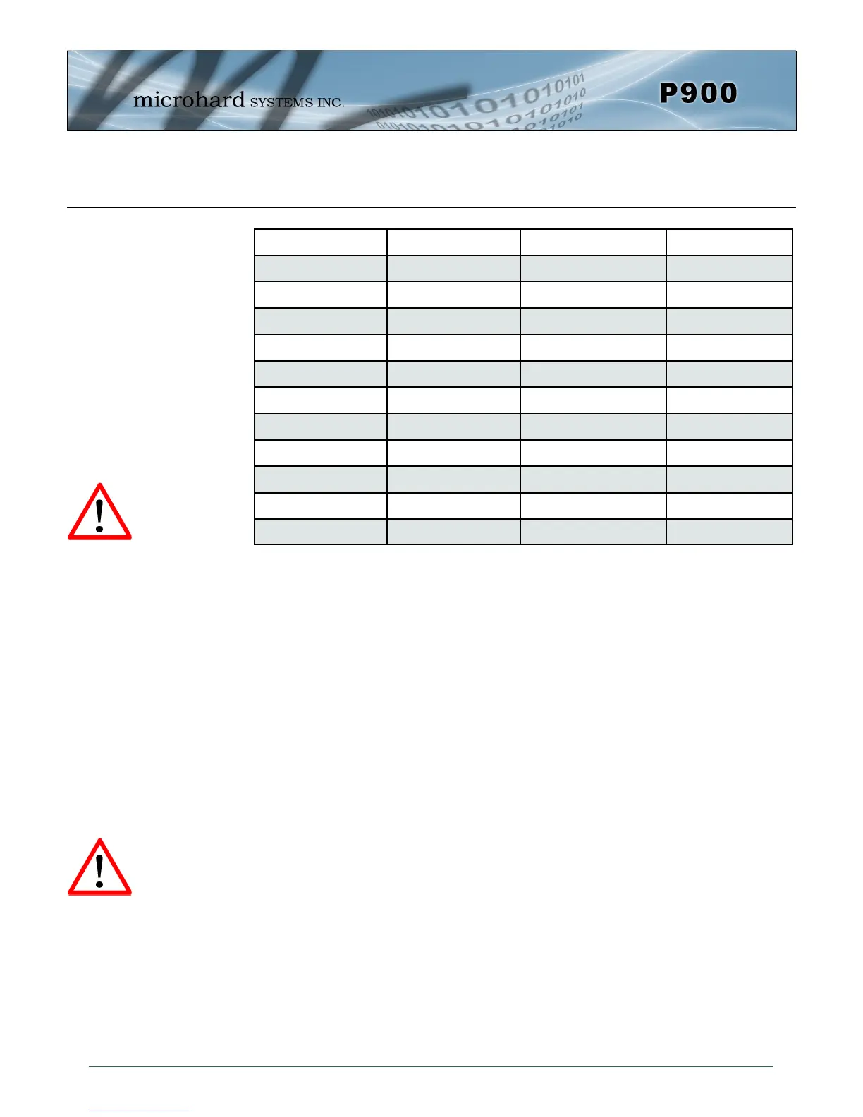
Table 5-1: Path Loss
Once the equipment is deployed, average receive signal strength may be determined
by accessing S Register 123.
To satisfy FCC radio
frequency (RF) exposure
requirements for mobile
transmitting devices, a
separation distance of 23cm
or more sh ou ld b e
maintained between the
antenna of this device and
persons during device
operation. To ensure
compliance, operation at
less than this distance is
not recommended. The
antenna used for this
transmitter must not be co-
located in conjunction with
any other antenna or
transmitter.
Never work on an antenna
system when there is
lightning in the area.
Distance (km) Master Height (m) Remote Height (m) Path Loss (dB)
5 15 2.5 116.5
5 30 2.5 110.9
8 15 2.5 124.1
8 15 5 117.7
8 15 10 105
16 15 2.5 135.3
16 15 5 128.9
16 15 10 116.2
16 30 10 109.6
16 30 5 122.4
16 30 2.5 128.8