© Microhard Systems Inc. Confidential 31
2.0 Hardware Description
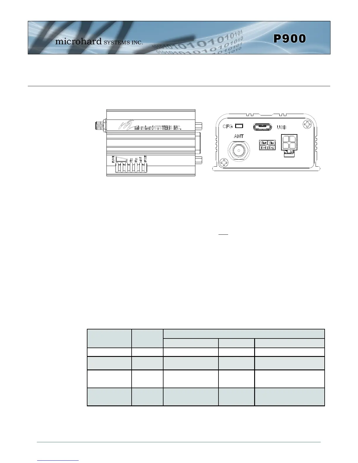
2.6.3 P900 Enclosed Connectors & LED Indicators
PWR (Blue)
This LED will illuminate when the P900 Enclosed is connected to a power source (9-30 VDC)
485 (Blue)
This LED will illuminate when the P900 Enclosed Data port is configured as a RS485 port.
(Register S142 Serial Channel Mode set to RS485 and Handshaking set to &K1)
TX LED (Red)
When illuminated, this LED indicates that the modem is transmitting data over the air.
RX LED (Green)
This LED indicates that the modem is synchronized and has received valid packets.
Receive Signal Strength Indicator (RSSI) (3x Green)
As the received signal strength increases, starting with the furthest left, the number of active
RSSI LEDs increases. Signal strength is calculated based on the last four valid received
packets with correct CRC. The value of RSSI is reported in S123.
MODE Unit Type
LED STATUS
RX/SYNC TX RSSI 1,2,3
COMMAND All OFF OFF OFF
DATA P.Coordinator
S.Coordinator
ON while receiving valid
data
ON while
Transmitting data
1-3 ON in proportion to signal
strength received from remotes.
DATA - during sync.
acquisition
S.Coordinator
Remote/
Standby
OFF OFF Cycling with 300ms ON time
DATA - when
synchronized
S.Coordinator
Remotes/
Standby
ON while synced ON when
transmitting
1-3 ON in proportion to signal
strength received from Coordinator
Table 2-16: LED Operation
Drawing 2-12: Connectors & LED’s (Top & End)