© Microhard Systems Inc. Confidential 33
3.0 Mesh Configuration
To begin configuration, the P900 must be mounted into a either a Microhard supplied devel-
opment board (with factory attached interface card), or be mounted into a customer designed
platform. The P900 is configured using AT commands through the Data port, or using special
diagnostic commands through the Diagnostic Port. Refer to Section 2: Hardware Descrip-
tion for information related to interfacing to, or powering the module.
To issue AT commands through the Data port, the P900 must first be set into Command
Mode as described below.
3.1 Configuration/Unit Modes
3.1.1 Command Mode
the P900 module is offline (data is not passing through the unit via it’s local data lines
or RF communications)
if installed in a Development Board, the only LED illuminated will be the blue power
LED.
the P900’s configuration options (registers) may be viewed and modified using AT
commands.
Two methods are typically used to place the Pico Series into Command Mode.
1. Force to Command Mode
Power down off the Development Board assembly.
Connect a 9-pin straight-through serial cable from the PC serial port to the rear RS-
232 port (DATA) of the modem.
Launch a terminal communications program (e.g. HyperTerminal) and configure for
9600 bps, 8 data bits, No parity, 1 stop bit (8N1), no flow control
press and hold the CONFIG button
continue to press the CONFIG button and apply power to the modem
release the CONFIG button
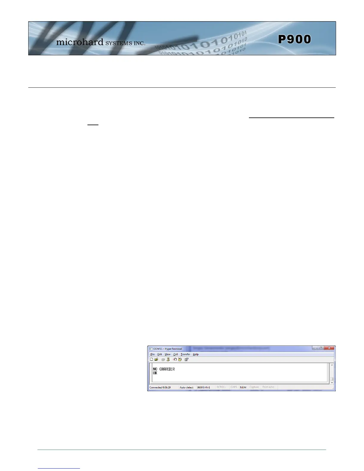
On power up the terminal session window should show “NO CARRIER OK” as seen
below:
the P900 is now in command mode, and AT commands can be used to configure or
query the settings. AT&V will display the current configuration, and the registers can
be queried using the ATSXXX=? Command where XXX = the register number. Help is
available using the ATSXXX /? Command.
Any and all changes must be written to NVRAM using the AT&W command.
Image 3-1: Command Mode