© Microhard Systems Inc. Confidential 64
4.0 Point to Point Configuration
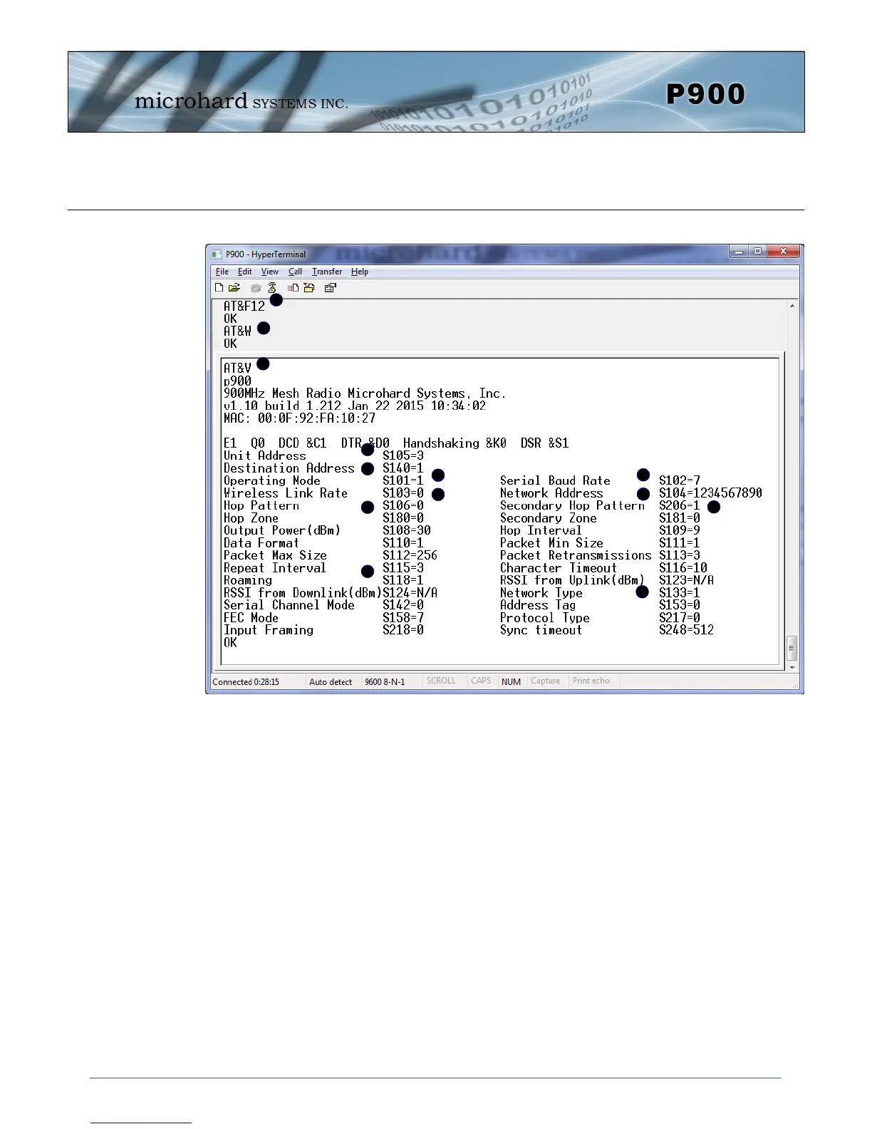
A) AT&F12 - Sets the factory defaults for a Point to Point Repeater.
B) AT&W - Writes the changes to NVRAM.
C) AT&V - Displays the configuration as seen above.
D) S105 - Every unit in a Point to Point Network must have a unique unit address. The address
of the Repeater is automatically set to 3.
E) S140 - The destination address is unit address of the final destination to which all data is to
be sent. In a Point to Point Network this address is set to 1, the unit address of the
master, and should not be changed.
F) S101 - The operating mode defines the unit type and is set to 1, which is a Repeater.
G) S103 - Wireless Link Rate must be set to the same value of each unit in the system.
H) S133 - The network type must be set to 1 for Point to Point operation. The content displayed
by the AT&V command varies with the network type.
I) S102 - The serial baud rate (and data format S110) must match that of the connected device.
J) S104 - Each unit in a Network must have the same Network Address. To change the
Network Address, the ATS104=XXXXXXX command can be used.
K) S106 - Ensure this register is set to the Hopping Pattern of the Master(S106), or if the unit is
to communicate through a repeater, set to match the Secondary Hop Pattern (S206).
L) S206 - This is the secondary hop pattern which is used to communicate with downstream
units.
M) S118 - The roaming address must be set to the master or repeaters’ address (if more than 1
repeater is used) in which this repeater is to synchronize with.
A
B
C
Image 4-7: AT&F12 Point to Point Repeater Configuration
AT&F12 Point to Point Repeater
D
E
F
G
H
I
J
K
L
M