© Microhard Systems Inc. Confidential 43
3.0 Mesh Configuration
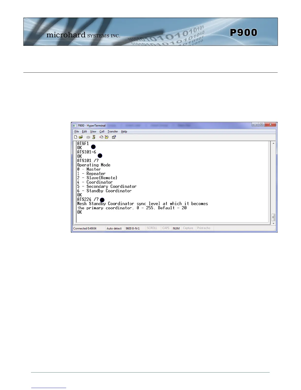
A) AT&F1 - Sets the factory defaults for a Primary Coordinator.
B) S101=6 - Changes Operating Mode to Standby Coordinator.
C) S224 - Standby Trip Level is used to specify how quickly the P900 will switch from
standby mode if sync packets are not received from the Primary.
The smaller the value of S224 the longer the Standby Coordinator will wait before assuming the role of
the Primary. The recommended value is 20% of the value of S248 on Primary coordinator. Note that
S248 on both Primary and Standby coordinators must be identical.
Remember, anytime registers are changed the values must be written to NVRAM using the AT&W com-
mand. To switch from command mode to data mode (online mode), the ATA command can be issued.
A
B
C
Image 3-7: Standby Coordinator
Standby Coordinator
Factory default settings are not available for the Standby Coordinator. The Standby Coordinator pro-
vides system redundancy if the Primary Coordinator fails. Generally the configuration of the Standby
Coordinator would be identical to that of the Primary Coordinator. For simple configuration, the AT&F1
command can be used to configure as a Primary Coordinator, then the Operating Mode (S101) changed
to Standby Coordinator. The Standby Trip Level can be adjusted by changing the value in register
(S224).