© Microhard Systems Inc. Confidential 48
3.0 Mesh Configuration
In the previous example (Drawing 3-6) we can see that Remote A and Remote B are in close proximity
of each other along an overlapping coverage boundary. Remote A can hear both the Primary and Sec-
ondary Coordinator. Even though it is closer to the Secondary Coordinator, it will associate with the Pri-
mary Coordinator as it has the lowest Rank. Remote B can only hear the Secondary Coordinator, so
obviously it can only associate with that coordinator. Without TX Profiling, there will be collision between
these units as they try to transmit. A TX profile will assign frames to each rank that they can use to send
data, without the worry that there will be collisions.
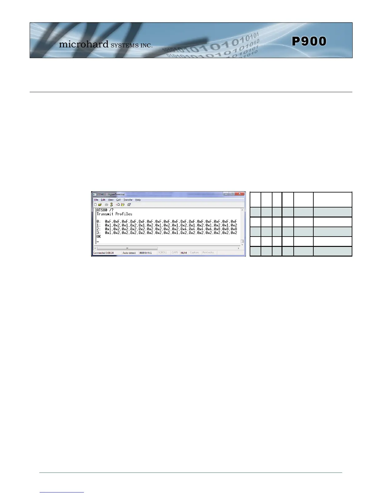
Currently there are 4 different TX Profiles. Querying the S80 register as seen below shows the TX Pro-
file. A TX Profile is a repeating pattern of 16 frames, each frame can be assigned a rank or combination
of ranks, which are allowed to transmit data during that frame. A value of 0xF, or F in hex means that
any unit can send data, essentially meaning that TX Profiling is not used for that frame and any rank
modem can send data.
As seen in the table each Hex Value in the pattern corresponds to a specific rank(s) able to transmit
during a specified frame. The TX Profile used can be set by using register S80, currently there are 4
different profiles. In future releases additional profiles may be available.
S80 = 0 - TX Profile (0-3)
Profile 0 allows any modem to send data regardless of rank, this essentially disables TX Profiling. This
is the default, as TX profiling is generally only useful in partially overlapping coverage areas where colli-
sion rates are high.
Profile 1 allows the bandwidth to be split equally between the Primary Coordinator and all rank 1 units.
This may be useful in system where there are no secondary coordinators, as there are no frames as-
signed to any units other than the Primary Coordinator and its’ associated units.
Profile 2 allows rank 1 units to have 1/2 of the bandwidth. The reason for this is in many systems, the
Primary Coordinator is generally located in a location that provides the greatest coverage, meaning it
generally has the most units associated with it. The rest of the bandwidth is split between the rank 2 and
rank 3 modems. The Primary Coordinator is given only 1 frame for occasional transmissions.
Profile 3 allocates most of the bandwidth to Rank 1 units with only 2 in 16 frames available for the Rank
0 coordinator. This profile is used in systems with no additional coordinators, where the units send data
a majority of the time, with the occasional transmission from the Primary.
Image 3-10: TX Profiles
R3 R2 R1 R0 TX
Profile
Description
0 0 0 1 0x1
Rank 0 can TX
0 0 1 0 0x2
Rank 1 can TX
0 1 0 0 0x4
Rank 2 can TX
1 0 0 0 0x8
Rank 3 can TX
1 1 1 1 0xF
All Ranks can TX
Table 3-1: TX Profiles