© Microhard Systems Inc. Confidential 109
Appendix E: Development Board Serial Interface
DCD Data Carrier Detect - Output from Module - When asserted (TTL low),
DCD informs the DTE that a communications link has been established
with another n920.
RX Receive Data - Output from Module - Signals transferred from the n920
are received by the DTE via RX.
TX Transmit Data - Input to Module - Signals are transmitted from the DTE
via TX to the n920.
DTR Data Terminal Ready - Input to Module - Asserted (TTL low) by the DTE
to inform the module that it is alive and ready for communications.
SG Signal Ground - Provides a ground reference for all signals transmitted by
both DTE and DCE.
DSR Data Set Ready - Output from Module - Asserted (TTL low) by the DCE
to inform the DTE that it is alive and ready for communications. DSR is
the module’s equivalent of the DTR signal.
RTS Request to Send - Input to Module - A “handshaking” signal which is
asserted by the DTE (TTL low) when it is ready. When hardware
handshaking is used, the RTS signal indicates to the DCE that the host
can receive data.
CTS Clear to Send - Output from Module - A “handshaking” signal which is
asserted by the DCE (TTL low) when it has enabled communications and
transmission from the DTE can commence. When hardware
handshaking is used, the CTS signal indicates to the host that the DCE
can receive data.
Notes: It is typical to refer to RX and TX from the perspective of the DTE. This should be kept in
mind when looking at signals relative to the module(DCE); the module transmits data on the
RX line, and receives on TX.
“DCE” and “module” are often synonymous since a module is typically a DCE
device.
“DTE” is, in most applications, a device such as a host microprocessor.
Arrows denote the direction that signals are asserted (e.g., DCD originates at the DCE and tells the DTE that
a carrier is present).
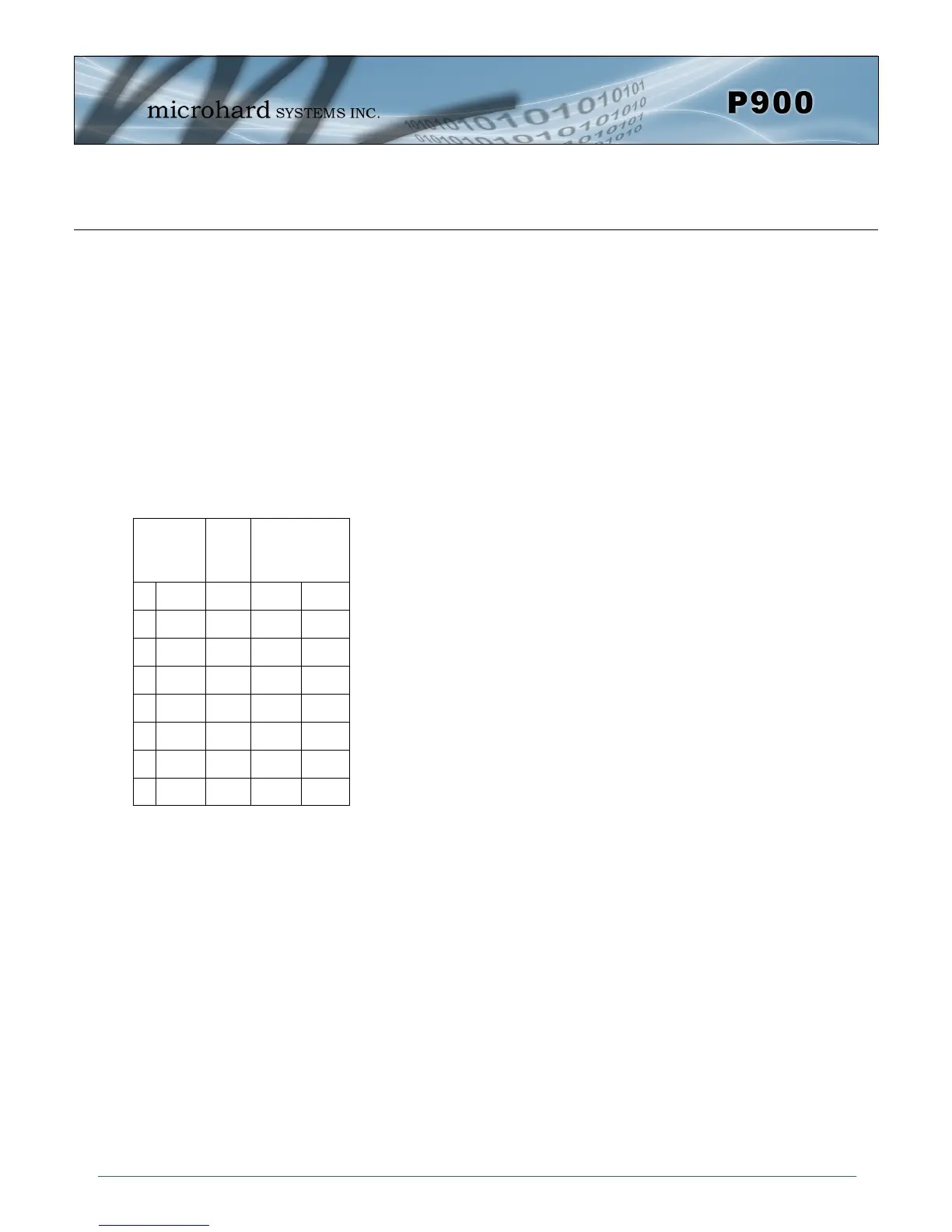
The P900 Serial Interface on the Development Board uses 8 pins on the header connector for asynchronous
serial I/O. The interface conforms to standard RS-232 signals without level shifting, so direct connection to a
host microprocessor is possible.
The signals in the asynchronous serial interface are described below:
Module
(DCE)
Signal
Host
Microprocessor
(DTE)
1 DCD
IN
2 RX
IN
3
TX OUT
4
DTR OUT
5 SG
6 DSR
IN
7
RTS OUT
8 CTS
IN
Table F1