© Microhard Systems Inc. Confidential 40
3.0 Mesh Configuration
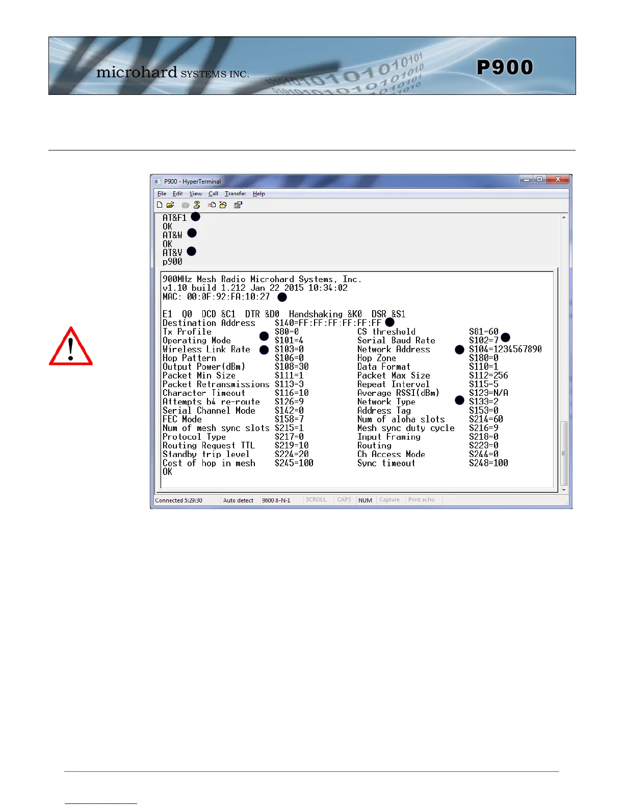
A) AT&F1 - Sets the factory defaults for a Primary Coordinator.
B) AT&W - Writes the changes to NVRAM
C) AT&V - Displays the configuration as seen above.
D) S101 - The Operating Mode is automatically set to 4, which is the value required for a Pri-
mary Coordinator.
E) S104 - Each unit in a Network must have the same Network Address. It is strongly
recommended to never use the default setting of 1234567890. To change the
Network Address, the ATS104=XXXXXXX command can be used.
F) S133 - The network type must be set to 2 or 3 for Mesh.
G) S140 - Destination Address. By default, the destination address is set to
FF:FF:FF:FF:FF:FF which means that any incoming data is broadcast to all devices.
For unicast this can be changed to the specific unit MAC Address.
H) MAC - Each Pico module has a factory set and defined MAC address which can be
viewed here.
I) S102 - The serial baud rate (and data format S110) must match that of the connected device.
J) S103 - Wireless Link Rate must be set to the same value of each unit in the system.
Higher link rates may result in higher throughput, but lower link rates usually
provide better sensitivity and overall robustness.
Remember, anytime registers are changed the values must be written to NVRAM using the AT&W com-
mand. To switch from command mode to data mode (online mode), the ATA command can be issued.
AT&F1 Primary Coordinator
A
B
C
G
D
E
F
Image 3-4: Factory Defaults AT&F1 - Primary Coordinator
H
I
J
Compression (S225)
was introduced in
firmware v1.10. S225
must be set to 0 for
compatibility with older
versions.