© Microhard Systems Inc. Confidential 24
2.0 Hardware Description
Output Driving Current
The GPIOs (general purpose input/outputs) can sink or source up to +/-8 mA, and sink
+20 mA (with a relaxed V
OL
).
In the user application, the number of I/O pins which can drive current must be limited to
respect the absolute maximum rating specified in Section 2.5.2:
● The sum of the currents sourced by all the I/Os on VDD cannot exceed the absolute maximum rating
I
VDD
(see Table 2-3).
The sum of the currents sunk by all the I/Os on VSS cannot exceed the absolute maximum rating I
VSS
(see Table 2-3).
Output Voltage Levels
Unless otherwise specified, the parameters given in Table 2-8 are derived from tests
performed under ambient temperature and V
DD
supply voltage ratings of the Pico Series. All I/Os are
CMOS and TTL compliant.
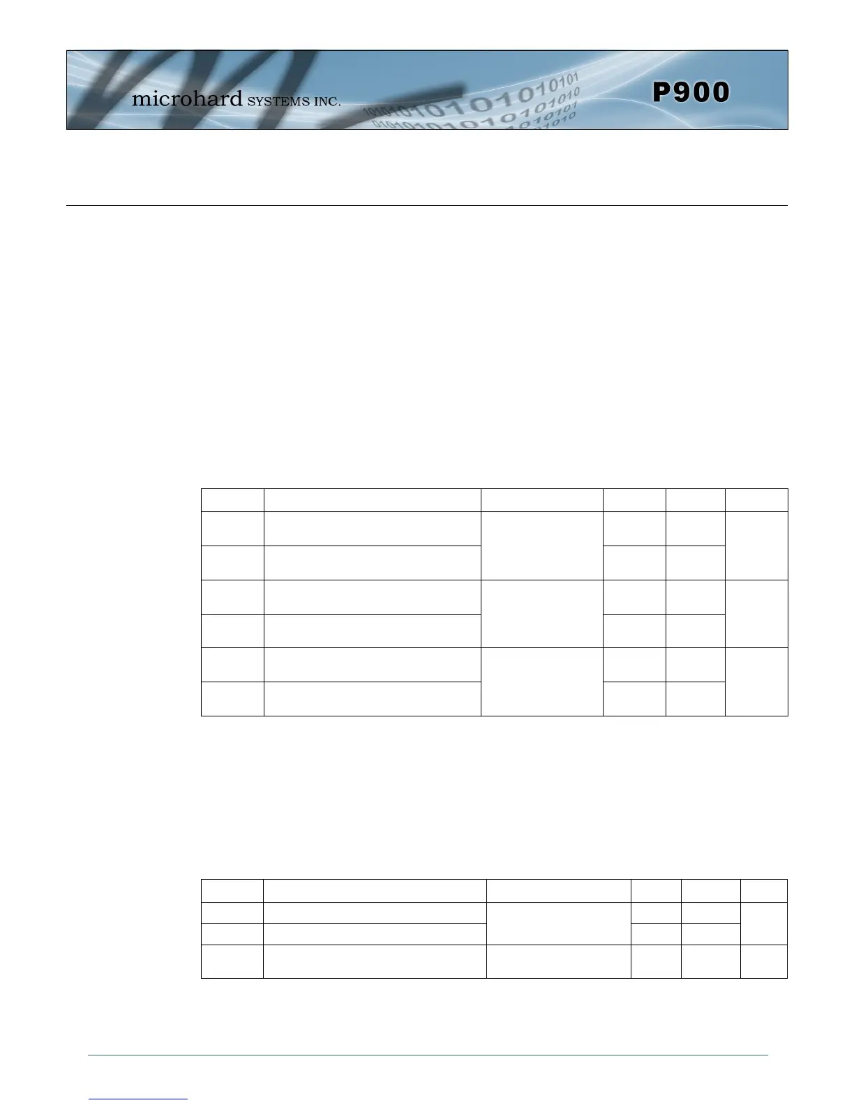
Input / Output AC Characteristics
The values of input/output AC characteristics are given in Table 2-9.
Symbol Parameter Conditions Min Max Unit
V
OL
(1)
Output low level voltage for an I/O pin
when 8 pins are sunk at same time
TTL port
I
IO
= +8mA
0.4
V
V
OH
(2)
Output high level voltage for an I/O pin
when 8 pins are sourced at same time
V
DD
-0.4
V
OL
(1)
Output low level voltage for an I/O pin
when 8 pins are sunk at same time
CMOS port
I
IO
= +8mA
0.4
V
V
OH
(2)
Output high level voltage for an I/O pin
when 8 pins are sourced at same time
2.4
V
OL
(1)(3)
Output low level voltage for an I/O pin
when 8 pins are sunk at same time
I
IO
= +20mA
1.3
V
V
OH
(2)(3)
Output high level voltage for an I/O pin
when 8 pins are sourced at same time
V
DD
-1.3
Table 2-10 Output Voltage Characteristics
1. The I
IO
current sunk by the device must always respect the absolute maximum rating specified in Table 2-3 and the sum of IIO (I/O ports and control
pins) must not exceed I
VSS
.
2. The I
IO
current sourced by the device must always respect the absolute maximum rating specified in Table 2-3 and the sum of I
IO
(I/O ports and
control pins) must not exceed I
VDD
.
3. Based on characterization data, not tested in production.
Symbol Parameter Conditions Min Max Unit
t
f(IO)out
Output high to low fall time
CL = 50 pF
125
ns
t
r(IO)out
Output low to high level rise time 125
t
EXTlpw
Pulse width of external signals used as
interrupts.
1 ms
Table 2-11 Input / Output AC Characteristics