© Microhard Systems Inc. Confidential 17
2.0 Hardware Description
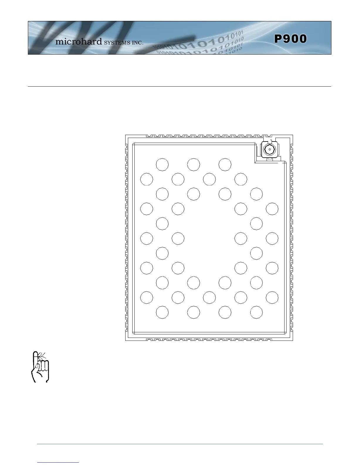
Drawing 2-5: Pico P900 80-pin OEM Connection Info
2.2 Pico OEM Pin Descriptions
The above drawing depicts a top view of the P900-OEM Module. The corner pads (1, 25, 41,
and 65) are printed directly on the bottom of the PCB for easy identification.
A full description of the connections and function of each pin is provided on the pages that
follow.
Inputs and outputs are
3.3V nominal (3.0V min
— 3.6V max) unless
otherwise specified.
GND
Vcc
Vcc
Vdd
Reserved
Reserved
Reserved
Reserved
Reserved
Reserved
Reserved
Reserved
Reserved
Reserved
Pico Series
P900
(Top View)
CANRX
CANTX
1
GND
DNC
DNC
DNC
DNC
DNC
USR1 - GPS/1PPS
USR2 - Alarm
USR3
I/O1
I/O2
I/O3
I/O4
USR AO0
USR AN0
USR AN1
GND
USBDP
USBDM
RSSI LED1
RSSI LED2
RSSI LED3
Reserved
2
3
4
5
6
7
8
9
10
11
12
13
14
15
16
17
18
19
20
21
22
23
24
40 39 38 37 36 35 34 33 32 31 30 29 28 27 26 25
41
42
43
44
45
46
47
48
49
50
51
52
53
54
55
56
57
58
59
60
61
62
63
64
80 79 78 77 76 75 74 73 72 71 70 69 68
67 66 65
LED RX
LED TX
GND
GND
GND
GND
GND
DNC
DNC
DNC
DNC
DNC
Reserved
Reserved
GND
GND
GND
Reserved
Wakeup_usr
!CONFIG
!RESET
RSMode
Reserved
Vbat
GND
GND
GND
Serial RING
Serial RxD
Serial TxD
Serial DSR
Serial CTS
Serial DTR
Serial DCD
Serial RTS
USR SCK
Reserved
Control RxD
Control TxD
GND
GND