© Microhard Systems Inc. Confidential 18
2.0 Hardware Description
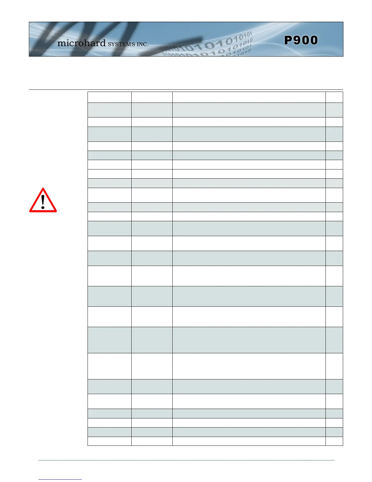
Pin Name No. Description
Dir
GND 1,17,25-26,39-
41,65-67,75-80
Ground reference for logic, radio, and I/O pins.
DNC 2,3,4,5,6 Reserved for factory use only.
USR1 –
GPS/1PPS
7
*Currently Not Supported. For Future Expansion*
I
USR2 - Alarm 8
*Reserved for future use.*
O
USR3 9
*Reserved for future use.*
O
I/O 1,2 10,11 Digital Outputs. 3.3 V Output @ 3mA maximum. O
I/O3,4 12,13 Future Use I/O
USR_ANO0 14
*Currently Not Supported. For Future Expansion*
O
USR_AN0
USR_AN1
15
16
Analog Inputs. 0 to 3V input, 12 bit. I
USBDP 18
*Currently Not Supported. For Future Expansion*
USBDM 19
*Currently Not Supported. For Future Expansion*
LED_1 (RSSI1) 20 Receive Signal Strength Indicator 1. Active high, cannot drive LED
directly. Requires current limiting resistor. 8mA maximum.
O
LED_2 (RSSI2) 21 Receive Signal Strength Indicator 2. Active high, cannot drive LED
directly. Requires current limiting resistor. 8mA maximum.
O
LED_3 (RSSI3)
22
Receive Signal Strength Indicator 3. Active high, cannot drive LED
directly. Requires current limiting resistor. 8mA maximum.
O
LED_RX 23 Active high output indicates receive and synchronization status.
Active high, cannot drive LED directly. Requires current limiting
resistor. 8mA maximum.
O
LED_TX 24 Active high output indicates module is transmitting data over the RF
channel. Active high, cannot drive LED directly. Requires current
limiting resistor. 8mA maximum.
O
Serial RING 27
Internally connected to GND through a 22kΩ resistor. In RS485
modes the RING line is set high and is normally used to enable the
receiver of the RS485 driver.
O
Serial RxD 28 Receive Data. Logic level input into the modem. It is recommended
to wire this pin out through a zero ohm resister to a header and
jumper block for external access to the serial port for modem
recovery procedures.
I
Serial TxD 29 Transmit Data. Logic level Output from the modem. It is
recommended to wire this pin out through a zero ohm resister to a
header and jumper block for external access to the serial port for
modem recovery procedures.
O
Serial DSR 30
Data Set Ready. Active low output. The DSR line may be used to
enable the transmitter of the RS485 driver chip.
O
Serial CTS 31
Clear To Send. Active low output. The CTS line may be used to
enable the transmitter of the RS485 driver chip.
O
Serial DTR 32 Data Terminal Ready. Active low input. I
Serial DCD 33 Data Carrier Detect. Active low output. O
Serial RTS 34 Request To Send. Active low input. I
USR SCK 35
*Currently Not Supported. For Future Expansion*
I
Table 2-3: Pico Series Pin Description
Caution: During power up
or reset, output pins from
the Pico are in an unknown
state. It is advised to use
pull up or pull down
resisters as appropriate.