© Microhard Systems Inc. Confidential 19
2.0 Hardware Description
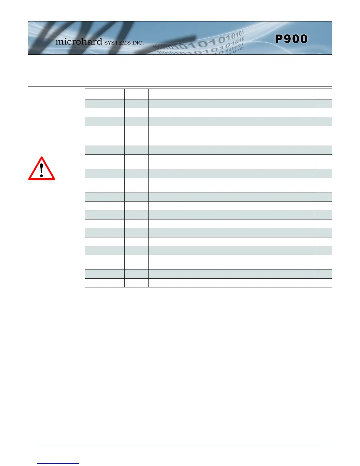
Pin Name No. Description
Dir
Reserved 36
*Reserved for future use.*
Control RxD 37 Diagnostics receive data. Logic level input from a PC to the module. I
Control TxD 38 Diagnostics transmit data. Logic level output from module to a PC. O
Vbat 42 Input voltage sensing analog input line, up to 60VDC maximum. Used to
measure the main supply voltage. User design must add a 10kΩ 1% 1/16W
resistor in series.
I
Reserved 43
*Reserved for future use.*
RSMode 44
Internally connected to GND through a 10kΩ resistor. *Reserved for future
use.*
O
!RESET 45 Active low input will reset the module. I
!CONFIG 46 Active low input signal to put module into default serial interface (RS232) and
default baud rate (9600/8/N/1) during power up. Pull high or leave floating.
I
!Wakeup_usr 47 Active high input used to wake the model from sleep mode. I
Reserved 48
*Reserved for future use.*
Reserved 49
*Reserved for future use.*
CANTX 50
*Currently Not Supported. For Future Expansion*
CANRX 51
*Currently Not Supported. For Future Expansion*
Reserved 52-61
*Reserved for future use.*
Vdd 62 Positive voltage supply voltage for the digital section of the module (3.3V). I
Vcc 63,64 Positive voltage supply voltage for the radio module (3.3V). The Vcc lines are
internally connected together.
I
Reserved 68,69
*Reserved for future use.*
DNC 70-74 Reserved for factory use only.
Table 2-3: Pico Series Pin Description (continued)
All serial communications signals are logic level (0 and 3.3V). DO NOT connect RS-232 level
(+12, -12VDC) signals to these lines without shifting the signals to logic levels.
Caution: During power up
or reset, output pins from
the Pico are in an unknown
state. It is advised to use
pull up or pull down
resisters as appropriate.