© Microhard Systems Inc. Confidential 32
2.0 Hardware Description
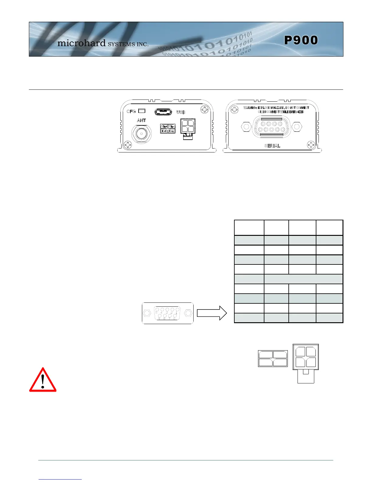
CFG Button
Holding this button while powering-up the modem will boot the unit into COMMAND mode:
the default serial interface will be active and temporarily set to operate at its default serial
settings of RS232 and 9600/8/N/1.
USB
Micro-AB USB Port. Internal USB to Serial Converter.
Provides access to the Serial Diagnostics Port.
The SERIAL (RS232/485 Port (DCE)) on the
Enclosed model is for:
RS232/485 Serial data when in DATA
MODE, or
for configuring the modem when in
COMMAND MODE.
Vin+/Vin– is used to power the unit. The input Voltage
range is 9-30 Vdc.
IO-1 / IO-2
Programmable I/O. Not currently supported in firmware.
Future Development.
ANT
RP-SMA Female Bulkhead Antenna connector.
Pin
No.
RS232
RS485
Full-Dup
RS485
Half-Dup
1 DCD
2 RXD TX- Data-
3 TXD RX+
4 DTR
5 Ground
6 DSR
7 RTS RX-
8 CTS TX+ Data+
9 N/C
Table 2-17: Data DB9 Pin Assignments
Caution: Using a
power supply that
does not provide
proper voltage may
damage the modem.
Drawing 2-13: Connectors & LED’s (Front & Back)