36 M32 - Digital Console User Manual 37
Monitor
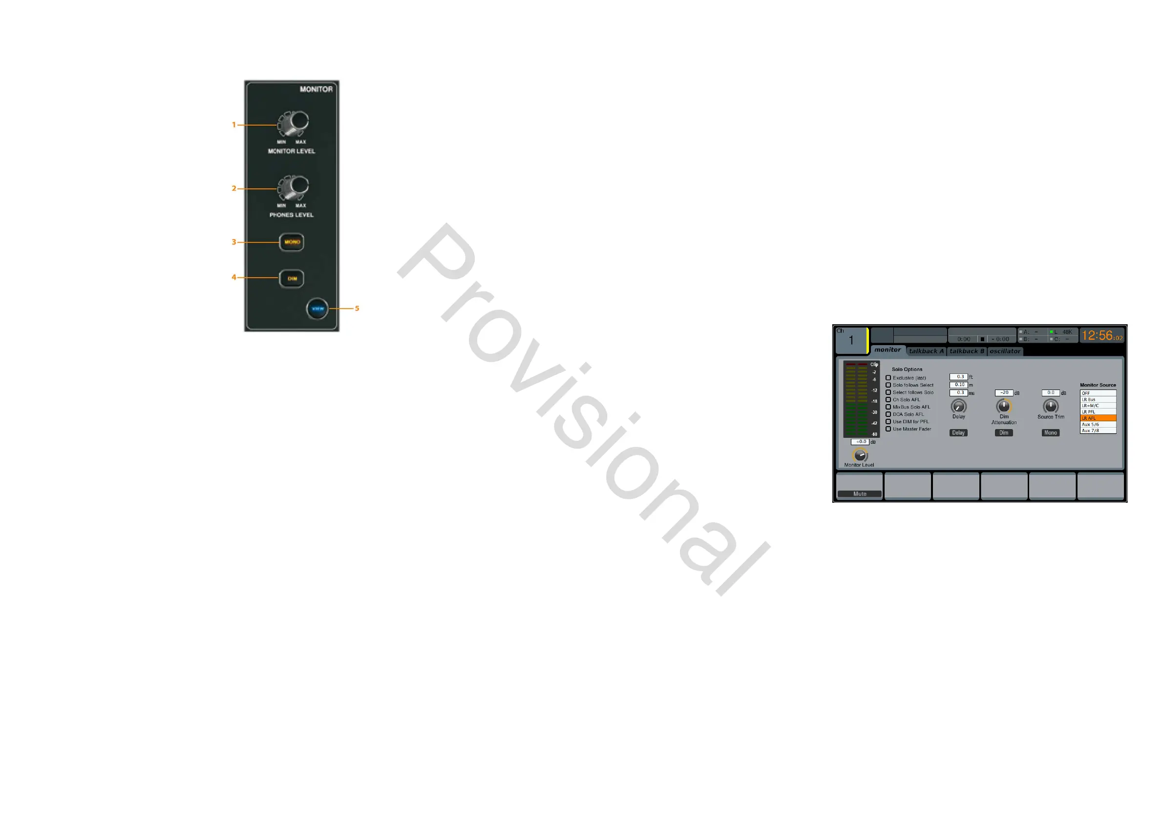
MONITOR LEVEL Rotary Control
Adjust the level of the monitor outputs with the MONITOR LEVEL rotary control. This will be the output device connected
to the sockets in the MONITOR / CONTROL ROOM OUT section on the rear panel.
PHONES LEVEL Rotary Control
Adjust the level of the signal through the headphones or other output devices connected via the headphone jack sockets
located under the front of the console.
MONO
Press the MONO button to monitor the audio signal in mono.
DIM
Press the DIM button to reduce the monitor volume by a predened amount. The amount of attenuation can be dened
via the Main Display when the VIEW button is pressed.
VIEW
Press the VIEW button to access more detailed parameters on the Main Display.
Operation
The MONITOR section shares a Main Display screen with the TALKBACK section. On this screen, only the monitor tab
1. Monitor Level Rotary Control
2. Phones Level Rotary Control
3. Mono Button
4. Dim Button
5. View Button
contains functionality which relates to the MONITOR section. This tab controls various console options relating to the solo
bus, as well as the console’s control room outputs. These options include various solo settings, speaker dimming, speaker
delay, and a selection of sources for the control room output.
To adjust the settings on the monitor tab, perform the following steps:
1. Adjust the rst rotary control to change the gain of the monitor signal. This digital stage occurs as a rst prelimi-
nary level control, before the top panel’s analogue-based monitor level control. A display above the rotary control
shows the currently set gain value in dB.
• A multi-segment level meter is displayed on the Main Display to allow for proper gain staging of the monitor
signal.
2. Adjust the second rotary control to scroll through the various solo methods available to the console when audio is
routed to the solo bus. Available options include:
• Exclusive (last): In this mode, pressing another SOLO button disengages the previous solo
• Solo Follows Select: When this method is selected, the audio of the currently selected channel will automat-
ically be sent to the solo bus. Since a user will often select a channel to adjust its dedicated DSP controls, this
method is useful because the audio of the channel will now already be feeding he solo bus where it can be
monitored with headphones in a live sound environment
• Select Follows Solo: When this
method is selected, any channel that
is soloed will automatically become
the currently selected channel
• Ch Solo AFL: The channel and select
button do not have any correlation to
each other. When a channel’s SOLO
button is pressed, its audio is sent
to the solo bus in ‘after-fader-listen’
mode, reecting the current level
of the channel fader and any chan-
nel DSP that has been applied. The
default setting for input channels is o for ‘pre-fader-listen’.
• MixBus Solo AFL: Selecting this method will set the mix bus solo to post-fader
• DCA Solo AFL: Selecting this method will set the DCA solo to post-fader
• Use DIM for PFL: Selecting this option will apply DIM to all PFL signals
• Use Master Fader: This allows the main fader/MUTE button to control the solo/mon output.
3. Tap the second control to select and assign the currently chosen solo option.
4. Turn the third control to adjust the amount of digital delay that is applied to the control room signal path. The
display on the screen will show the current amount of delay in feet, metres and milliseconds.
5. Tap the third control to toggle the delay function on or o.
TIP: The delay function is useful for aligning the sound of audio monitored through headphones, or speakers used at front-
of-house position with audio that is coming from the stage location.
By delaying the control room audio, it can be brought into alignment with the slightly-delayed audio that has to travel
from the stage to the front-of-house position.
www.theaudiospecialists.eu