52 M32 - Digital Console User Manual 53
Home
The HOME screen contains a high-level overview of the selected input or output channel, and oers various adjustments
not available through the dedicated top-panel controls.
The HOME screen is divided into the following tabs:
home: General signal path for the selected input or output channel.
cong: Allows selection of signal source/destination for the channel, conguration of insert point, and other
settings.
gate: Controls and displays the channel gate eect beyond those oered by the dedicated top-panel controls.
dyn: Controls and displays the channel dynamics eect (compressor) beyond those oered by the dedicated
top-panel controls.
eq: Controls and displays the channel EQ eect beyond those oered by the dedicated top-panel controls.
sends: Controls and displays the channels sends, such as sends metering and sends muting.
main: Controls and displays the selected channel’s output.
home
The home tab of the HOME screen displays a
general signal path for the currently selected in-
put or output channel. It visually displays various
parameters of the input, gate, insert point, EQ,
dynamics, output path and buses.
The home tab contains the following param-
eters (divided into two pages) that can be
adjusted using the six rotary controls.
Page 1
1. Turn the rst rotary control to adjust the
input gain (trim) of the channel.
2. Tap the rst control to link the channel with its adjacent channel.
3. Adjust the second control to set the threshold of the channel noise gate.
4. Tap the second control to toggle the channel noise gate in/out of the signal path.
5. Adjust the third control to toggle the channel’s insert point between pre-fader and post-fader status.
6. Tap the third control to toggle the channel insert in/out of the signal path.
7. Adjust the fourth control to toggle the channel dynamics between pre-EQ and post-EQ status.
8. Tap the fourth control to toggle the channel EQ in/out of the signal path.
9. Adjust the fth control to set the threshold of the channel compressor.
10. Tap the fth control to toggle the channel compressor in/out of the signal path.
11. Adjust the sixth control to pan the selected channel within the main stereo output.
12. Tap the sixth control to assign the selected channel to the main stereo output.
Page 2
1. Adjust the rst rotary control to select the console channel currently controlled by the HOME screen.
2. Tap the rst control to toggle +48V phantom power on/o for the currently selected input.
3. Tap the second control to toggle the phase ip on/o for the currently selected channel.
4. Adjust the third control to select to which of the eight DCA groups the currently selected channel will be assigned.
5. Tap the third control to assign the currently selected channel to the selected DCA group.
6. Adjust the fourth control to select to which of the six mute groups the currently selected channel will be assigned.
7. Tap the fourth control to assign the currently selected channel to the selected mute group.
8. Tap the fth control to toggle solo on/o for the currently selected channel.
9. Turn the sixth control to adjust the fader level for the currently selected channel.
10. Tap the sixth control to toggle mute on/o for the currently selected channel.
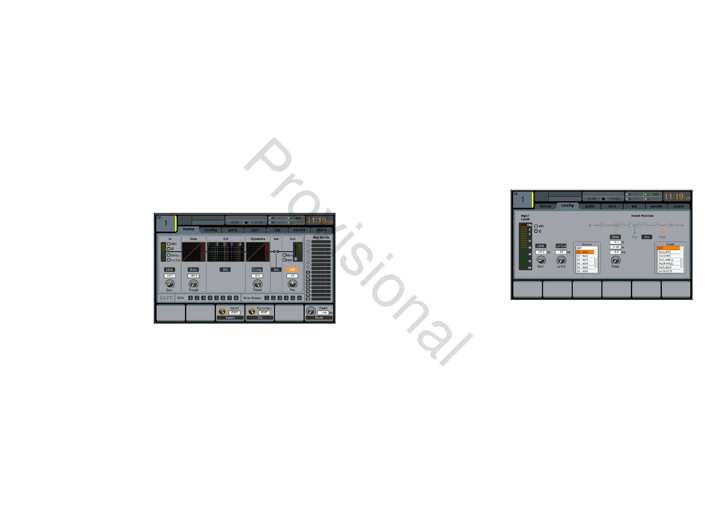
cong
The conguration tab allows selection of signal
source/destination for the channel, conguration
of insert point, and other settings, as well as
conguration of the channel delay.
The cong tab contains the following param-
eters that can be adjusted using the six rotary
controls:
1. Turn the rst rotary control to adjust the
input gain (trim) of the channel.
2. Tap the rst control to allow linking of the
channel to the adjacent channel.
3. Adjust the second control to set the low-cut frequency of the channel.
4. Tap the second control to toggle the low-cut lter in/out of the signal path.
5. Adjust the third control to scroll among all of the possible sources for the channel.
6. Tap the third control to select the currently highlighted source and assign it to the channel.
7. Adjust the fourth control to set the amount of digital line delay applied to the channel.
8. Tap the fourth control to toggle the delay in/out of the signal path.
9. Adjust the fth control to toggle the channel insert between pre- and post-EQ/compressor.
10. Tap the fth control to toggle the channel insert in/out of the signal path.
11. Adjust the sixth control to scroll among the signal path choices for the insert point.
12. Tap the sixth control to assign the selected signal path to the insert point.
www.theaudiospecialists.eu