68 M32 - Digital Console User Manual 69
xlr out
The ROUTING screen’s xlr out tab, much like the out 1-16 tab, allows the user to patch the M32’s various internal sig-
nal paths to the 16 analogue XLR outputs that are located on the console’s rear panel. This tab, however, allows the XLR
outputs to be patched in blocks of four, rather than individually. Also, on this screen it is only possible to route the signal to
its absolute destination, rather than choosing the signal path. The available destinations will dier depending on the block
selected. Destinations include:
Block 1-4 / Block 9-12
• Local 1-4
• Local 9-12
• Local 17-20
• Local 25-28
• AES50-A 1-4
• AES50-A 9-12
• AES50-A 17-20
• AES50-A 25-28
• AES50-A 33-36
• AES50-A 41-44
• AES50-B 1-4
• AES50-B 9-12
• AES50-B 17-20
• AES50-B 25-28
• AES50-B 33-36
• AES50-B 41-44
• Card 1-4
• Card 9-12
• Card 17-20
• Card 25-28
• Out 1-4
• Out 9-12
• P16 1-4
• P16 9-12
• Aux 1-4
• Auxin 1-4.
Block 5-8 / Block 13-16
• Local 5-8
• Local 13-16
• Local 21-24
• Local 29-32
• AES50-A 5-8
• AES50-A 13-16
• AES50-A 21-24
• AES50-A 29-32
• AES50-A 37-40
• AES50-A 45-48
• AES50-B 5-8
• AES50-B 13-16
• AES50-B 21-24
• AES50-B 29-32
• AES50-B 37-40
• AES50-B 45-48
• Card 5-8
• Card 13-16
• Card 21-24
• Card 29-32
• Out 5-8
• Out 13-16
• P16 4-8
• P16 13-16
• Aux 5-6/Mon
• Auxin 5-6/TB.
Setup
The SETUP screen oers various controls for global, high-level functions of the M32, such as display adjustments, sample
rates and synchronisation, user settings, and network conguration.
The SETUP screen contains the following separate tabs:
global: This screen oers adjustments for various global preferences of how the console operates.
cong: This screen oers adjustments for sample rates and synchronisation, as well as conguring high-level
settings for signal path buses.
remote: This screen oers dierent controls for setting up the console as a control surface for various DAW record-
ing software packages on a connected computer.
network: This screen oers dierent controls for attaching the console to a standard Ethernet network.
scribble strips: This screen oers controls for various aspects of the console’s DCA groups.
preamps: This screen allows the gain on each of the individual input channels’ preamps to be adjusted.
card: This screen selects between the USB and FireWire connectors, and also selects the input/output congura-
tion.
None of the SETUP screen’s tabs contain a secondary level of functionality, so the UP/DOWN navigation controls do no
need to be used for these screens.
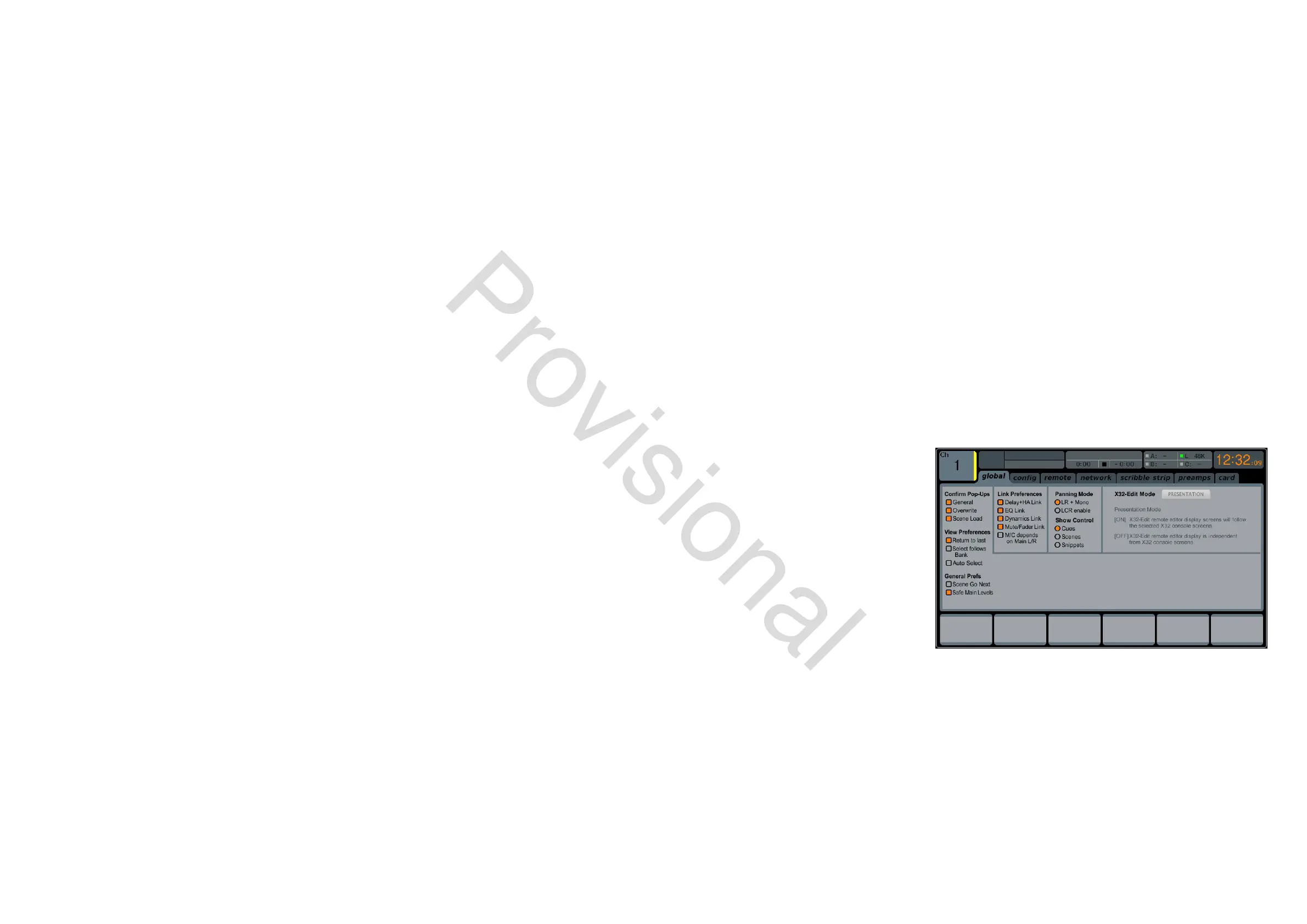
global
The SETUP screen’s global tab allows the user to
adjust various global controls of the console, such
as display brightness and contrast, the panning
mode used by channels, text languages, and
more.
To make adjustments to the global screen,
perform the following steps:
1. Adjust the rst rotary control to select var-
ious console settings for pop-up messages
and assorted preferences.
2. Tap the rst control to turn the currently
selected setting on or o.
3. Adjust the second control to select settings for linking multiple console channels.
4. Tap the second control to turn the currently selected setting on or o.
5. Adjust the third control to set the console’s panning mode, which aects how channel panning is performed in the
stereo eld. The ve choices are:
• LR+M: This is the default mode of the console. In this mode, channels can be panned between left and right
mix outputs, as well as assigned to the separate mono mix bus. In this mode the Centre/Mono bus is not
aected by the pan control
• LCR: In this mode, the signal is panned from left to right. This behaviour is emulated by the faders on the Main
tab, which is more intuitive than on other consoles. Note that in this mode, the denition of ‘mono’ changes,
www.theaudiospecialists.eu