17
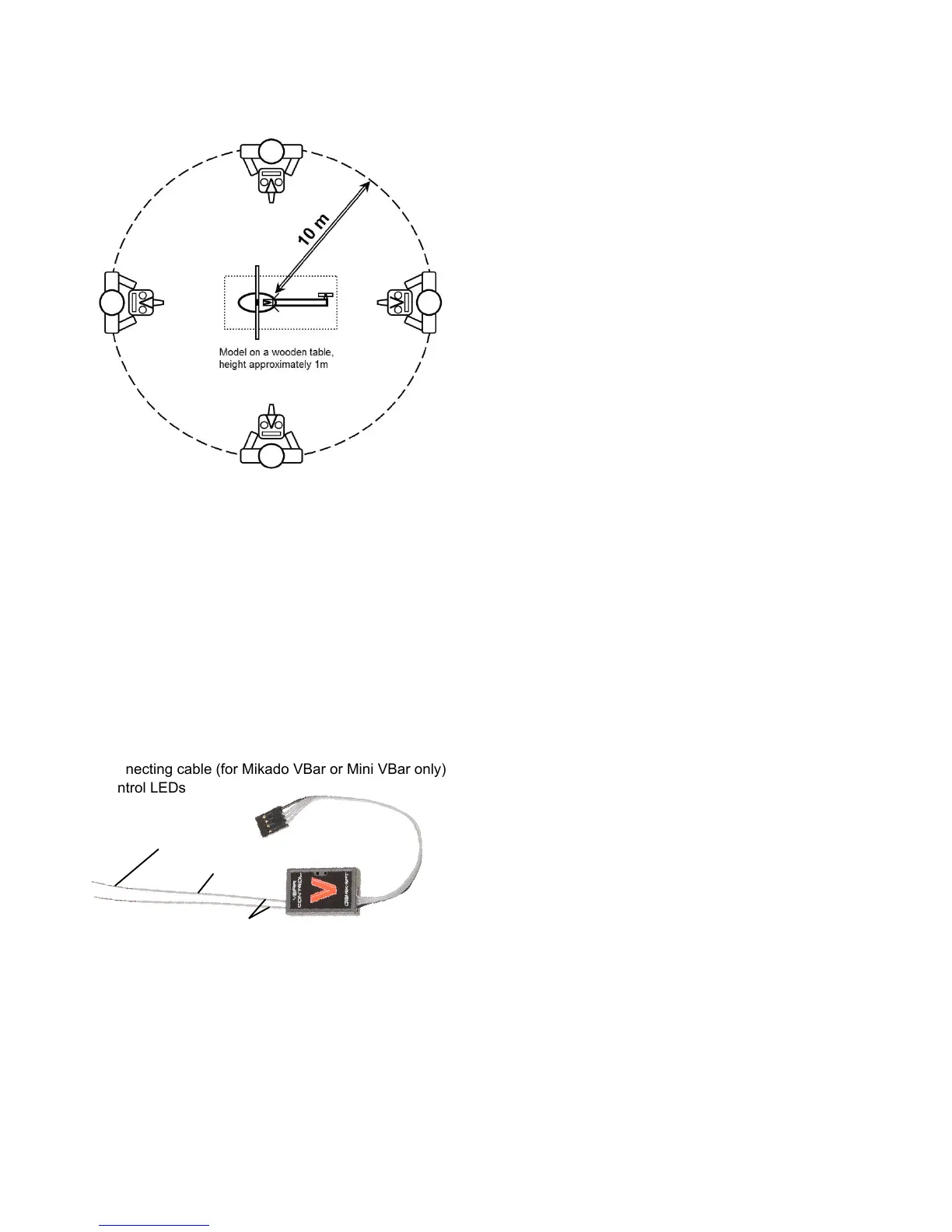
For a range check, walk around your model in a 30 ft/10 m
radius. Point the antenna of VBar Control at the model as
if you were ying it. Link power may not read below the
vertical threshold line.
⚠ If link power falls below the vertical threshold line, re-ar-
range the antennae and repeat the test.
☒ Do not place the model onto a metal surface for this test.
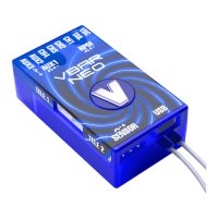
VBar Control Satellite
Receiver
■ Antennae
» Coaxial antenna wire
» Actual antenna wire
■ Connector
■ Connecting cable (for Mikado VBar or Mini VBar only)
■ Control LEDs
☝ Attention The black coded wire connects to the black mark
of the Control Panel Connector of a VBar main unit or to the
triangle mark on a Mini VBar.
■ The green LED signals that the receiver is bound to
and synchronized with VBar Control.
■ The red LED ashes when data are being sent, e.g.
telemetry is active.
■ Place the receiver next to the VBar Flybarless control-
ler.
■ Fix it using e.g. double-sided adhesive tape or velcro
tape. Make sure it does not touch the frames/chassis
directly to avoid vibration inuence.
■ Avoid places where liquids could spill on the receiver,
take waterproong measures if necessary.
■ Avoid places where high temperature changes can
occur.
■ Take measures so wires or antennae do not get
damaged e.g. by sharp-edged carbon ber or alumi-
num frames.
■ Make sure the connector is securely attached and the
wire is not subject to tension and that they are not bent
or kinked.
■ Place the antennae in a way so the actual antennae do
not touch frames or chassis elements. The free space
around the tip should have the size of a table tennis
ball.
■ If the actual antennae touch conductive or shielding
material such as metal or carbon ber surfaces, the
reception will be reduced considerably.
■ Align the antennae in a way so they point at a 90°
angle.
■ Separate the antenna tips as far as possible, their
mutual distance is even more important than achieving
a 90° angle.
■ Do not unnecessarily cover the actual antennae.
■ Do not bend or kink the actual antennae.
■ The coaxial wires may be bent, but only in a gentle arc,
not 90° sharp, so as not to damage the actual antenna
wire inside.
■ Separate the antennae as far as possible from electric
motors, electronic speed controllers or other sources of
electric/electronic noise.
■ Separate the antennae as far as possible from conduc-
tive or shielding materials/surfaces. When installed
inside a fuselage, try and place the antenna tips
outside the fuselage.
☝ If you are mounting the VBar Control Satellite inside a fus-
alage, always perform a comprehensive range check.
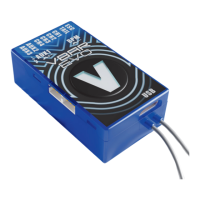
Antennae
Coaxial antenna wire
Connecting cable
Control LEDs
Actual antenna wire

 Loading...