System Overview 2-9
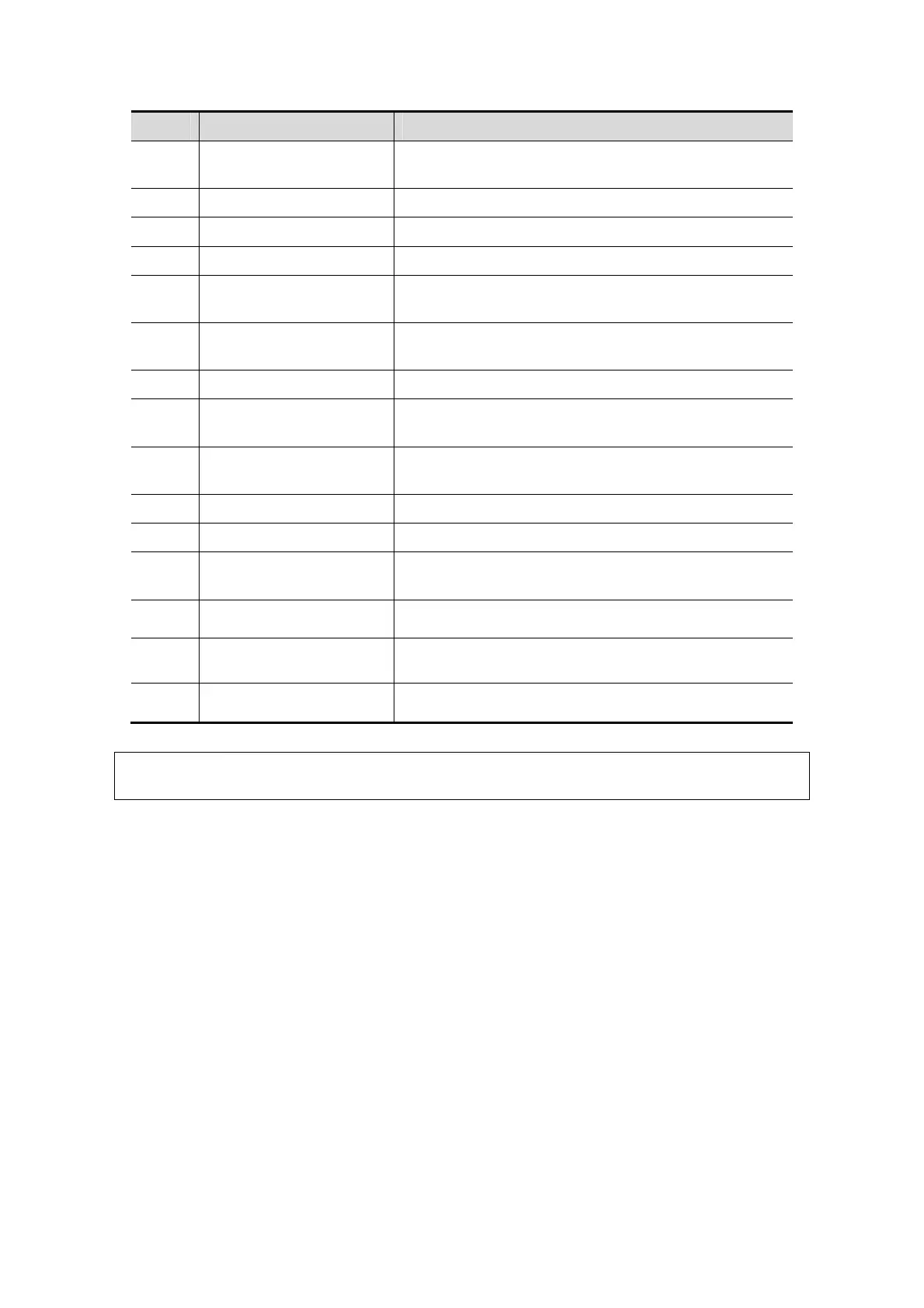
No. Name Function
10.
Control panel adjusting
lever
Used for lifting or swiveling the control panel.
11. USB USB port
12. Hanger /
13. Intracavitary probe holder Used for fixing the intracavitary probe.
14.
Ultrasound gel holder/gel
warmer
Used for placing the ultrasound gel or installing the gel
warmer.
15. Physio panel
Used for connecting the ECG leads and external ECG
device.
16. Probe port Sockets connecting transducers and the main unit.
17. Monitor supporting arm
Supports the monitor, for adjusting the height and
position of the monitor.
18.
Control panel supporting
arm
Supports the control panel, for adjusting the height of
the panel.
19. Rear handle Used for pushing and moving the system.
20. Cooling vent /
21. I/O Panel
Interface panel used for inputting and outputting
signals.
22.
Power supply panel
Electrical port panel.
23.
Caster lock
Lock the caster. The device keeps stable when four
casters are locked.
24.
Tray
Place the stuff or peripherals.
NOTE: Do not overexert to push down or lift up the control panel when operate the control
table adjusting handle.