EasyManuals Logo

Mindray DC-40 User Manual

Mindray DC-40
303 pages
To Next Page IconTo Next Page
To Previous Page IconTo Previous Page
Page #36 background imageLoading...
Page #36 background image
2-10 System Overview
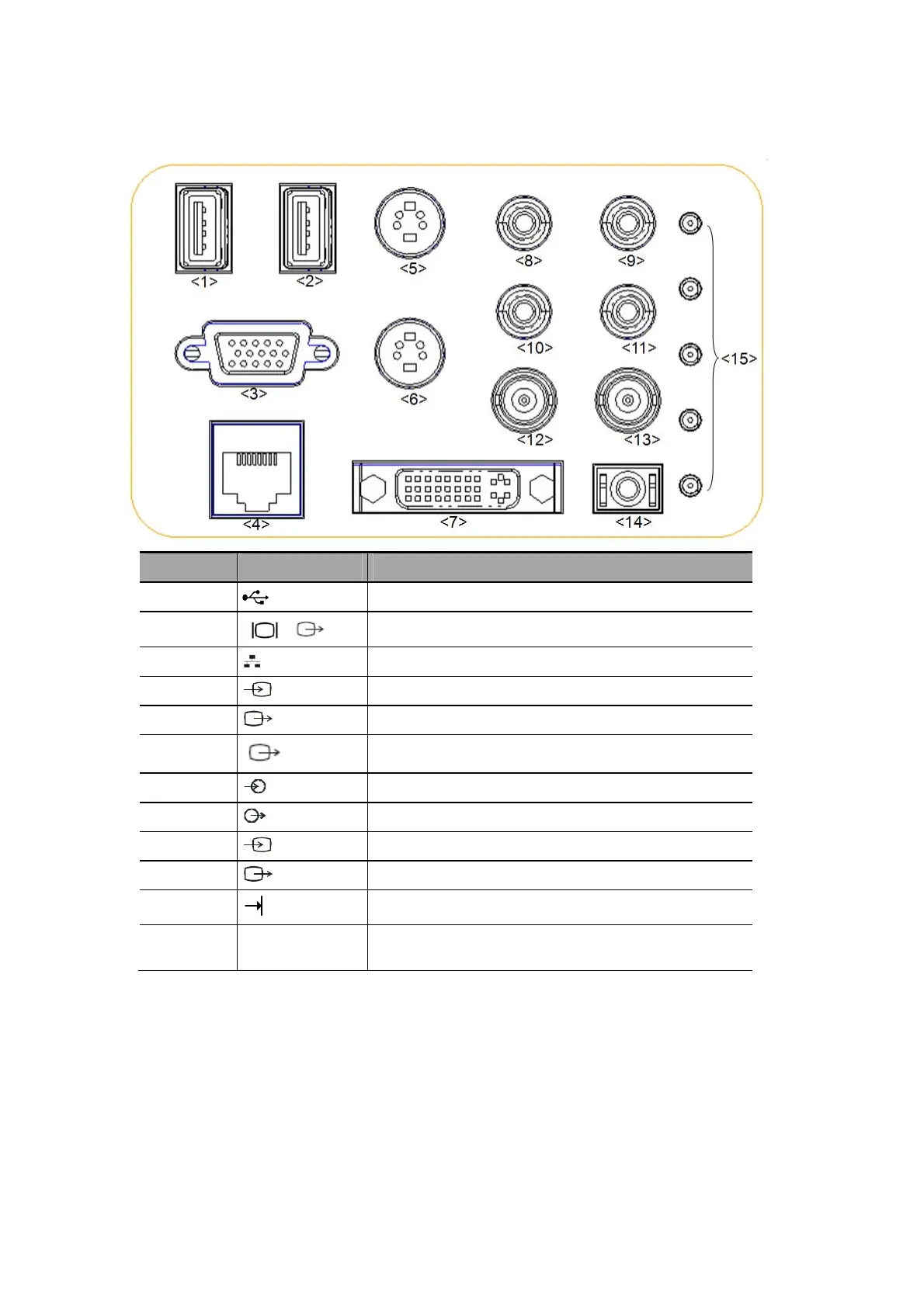
2.7 I/O Panel
No. Symbol Function
<1><2>
USB port, used for connecting USB devices.
<3>
VGA signal output; connects a monitor or projector.
<4>
Ethernet interface.
<5>
Separate video input (reserved).
<6>
Separate video output.
<7>
DVI signal output.
<8><9>
Audio signal input port, left channel(reserved).
<10><11>
Audio signal output port, right channel.
<12>
Used for
composite video input (reserved).
<13>
Used for
composite video output.
<14>
Remote interface for connecting video printer.
<15>
Malfunction
indication lights
Indicate the system’s malfunction.

Table of Contents

Questions and Answers:

Question and Answer IconNeed help?

Do you have a question about the Mindray DC-40 and is the answer not in the manual?

Mindray DC-40 Specifications

General IconGeneral
Touch ScreenYes
Hard Drive500 GB
3D/4D ImagingYes
Storage Temperature-20°C to +60°C
Operating Temperature+10°C to +40°C
Atmospheric Pressure700 hPa to 1060 hPa
Imaging ModesB, M, Color Doppler, Power Doppler
ProbesConvex, Linear, Phased Array
ConnectivityDICOM, USB, Ethernet
Power Supply100-240V AC, 50/60Hz
Display15-inch color LCD

Related product manuals