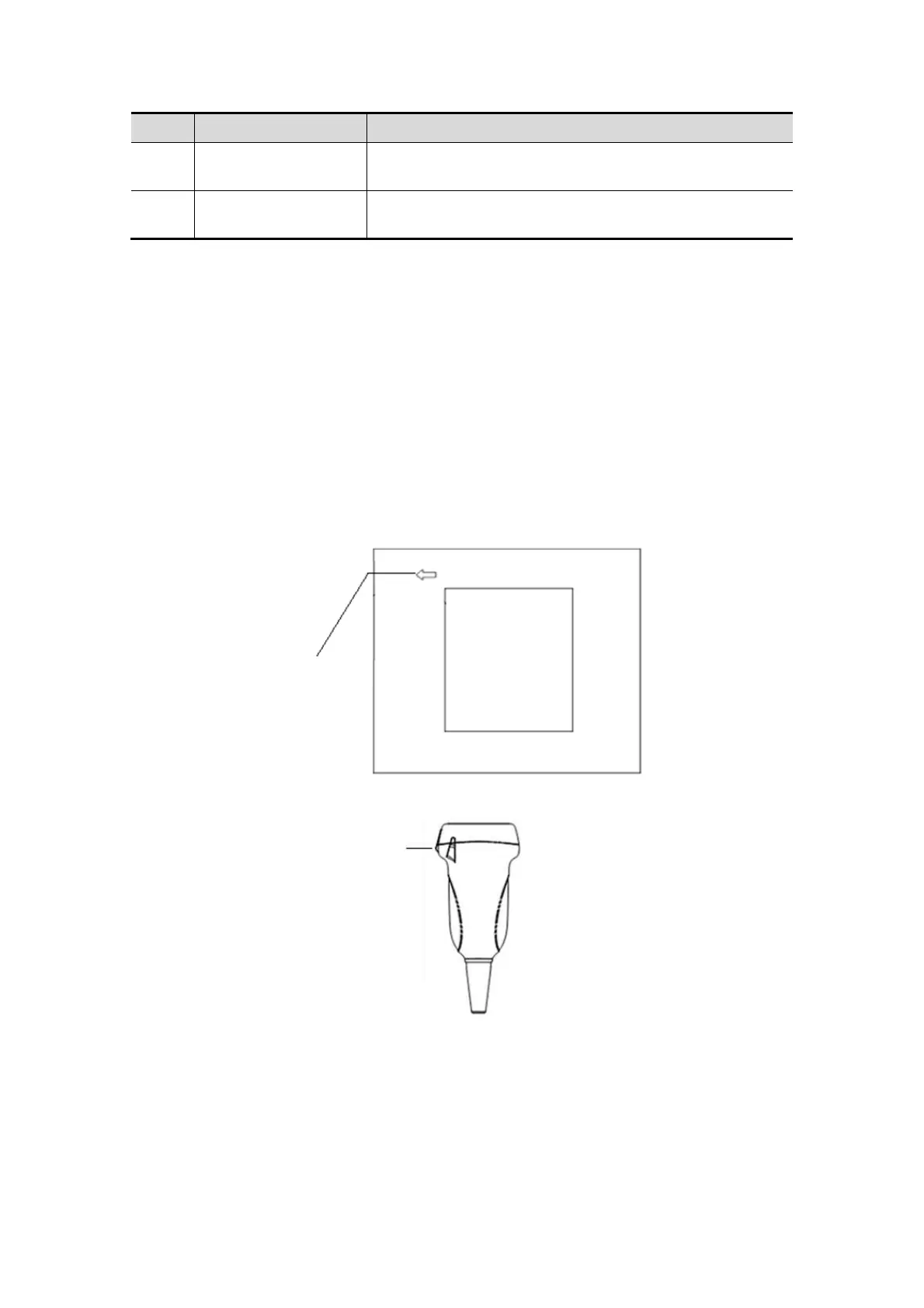
13-6 Probes and Biopsy
No. Name Function
<3> Probe cable
Used to transmit electrical signals between the probe
body and connector.
<4> Probe connector
Used to connect the probe to the ultrasonic diagnostic
system.
Tips:
The probes’ structure marked <2> in the figure above may vary with the matched
needle-guided brackets.
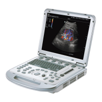
13.1.2 Orientation of the Ultrasound Image and the
Probe Head
The orientation of the ultrasound image and the probe are shown as below. The “Mark”
side of the ultrasound image on the monitor corresponds to the mark side of the probe.
Check the orientation before the examination (Here takes linear probe as an example).
13.1.3 Procedures for Operating
This section describes general procedures for operating the probe. The proper clinical
technique to be used for operating the probe should be selected on the basis of
specialized training and clinical experience.
Mark
Orientation mark