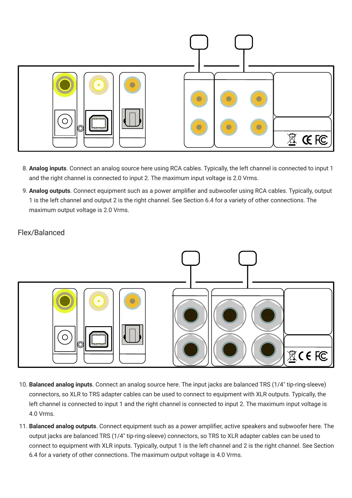
. Analog inputs. Connect an analog source here using RCA cables. Typically, the left channel is connected to input 1
and the right channel is connected to input 2. The maximum input voltage is 2.0 Vrms.
9. Analog outputs. Connect equipment such as a power amplier and subwoofer using RCA cables. Typically, output
1 is the left channel and output 2 is the right channel. See Section 6.4 for a variety of other connections. The
maximum output voltage is 2.0 Vrms.
Flex/Balanced
10. Balanced analog inputs. Connect an analog source here. The input jacks are balanced TRS (1/4" tip-ring-sleeve)
connectors, so XLR to TRS adapter cables can be used to connect to equipment with XLR outputs. Typically, the
left channel is connected to input 1 and the right channel is connected to input 2. The maximum input voltage is
4.0 Vrms.
11. Balanced analog outputs. Connect equipment such as a power amplier, active speakers and subwoofer here. The
output jacks are balanced TRS (1/4" tip-ring-sleeve) connectors, so TRS to XLR adapter cables can be used to
connect to equipment with XLR inputs. Typically, output 1 is the left channel and 2 is the right channel. See Section
6.4 for a variety of other connections. The maximum output voltage is 4.0 Vrms.