•
•
•
•
•
•
Product presentation
MiR200™ User Guide, Robot interface 2.0, 11/2018 v.1.2 20
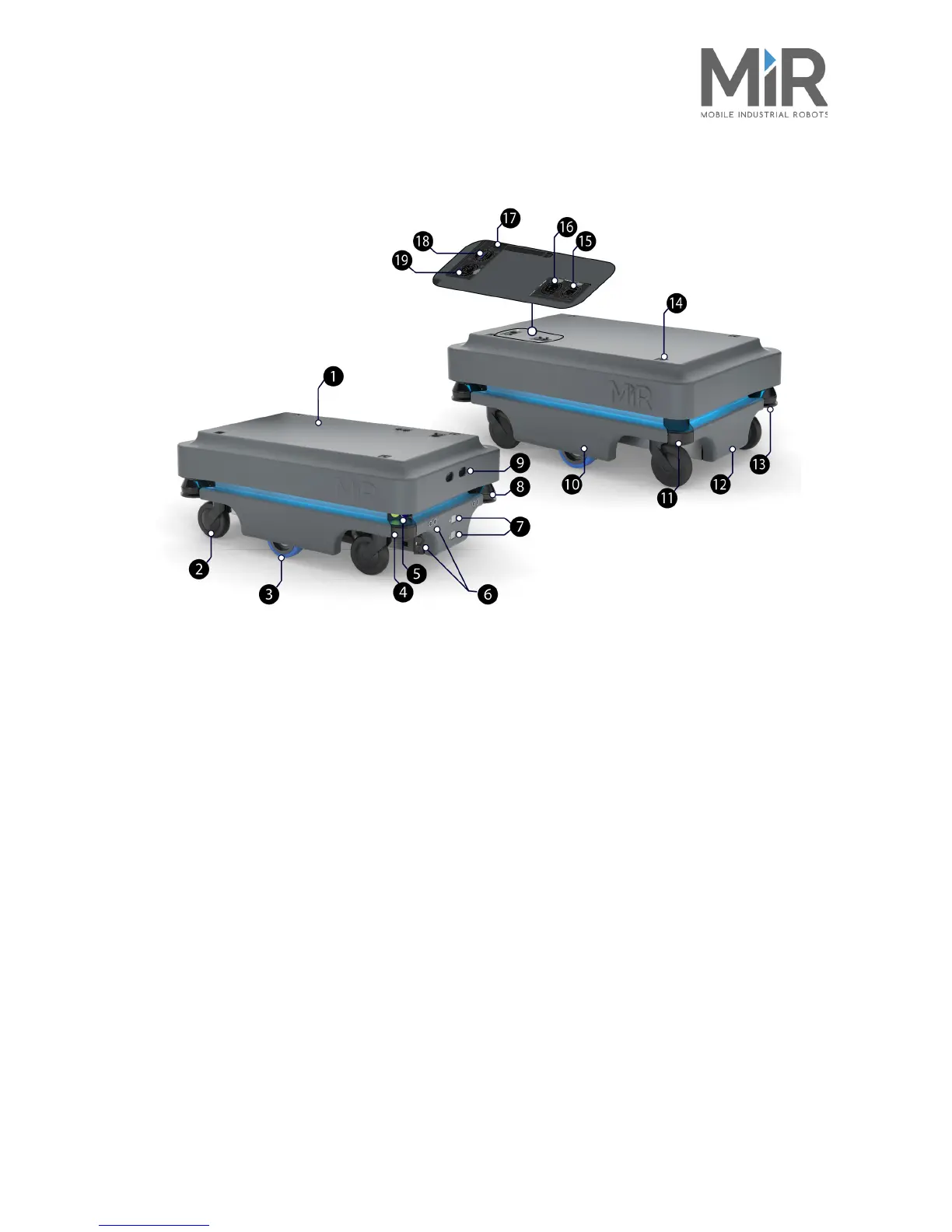
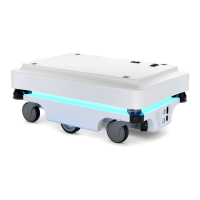
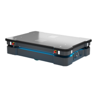
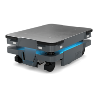
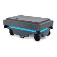
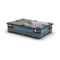
5.3 MiR200™ Outer parts
Figure 5.2. MiR200™ Outer parts
1. Top cover 11. Behind removable rear corner cover: Charging
port with switch
2. Caster wheel - all four corner wheels 12. Rear cover
3. Drive wheel - differential control 13. Rear laser scanner
4.
Behind removable corner cover: HDMI port and
USB port “service port” - connects to the robot’s PC
14. Mooring hole - one in each corner for fixation of
top modules
5. Scanner reset button (yellow) and on/off button
(blue)
15. RJ45 Ethernet connection
6. Ultrasonic sensors for detection of transparent
objects
(feature in progress).
16. Application interface - for connection to hardware
such as hook - see also Appendix C, Connectors -
pinout on page 38
7. Pad connectors - for connection to charging poles
on MiRCharge charging station
17. Antenna socket
8. Front laser scanner 18. USB port “service port” - connects to the robot’s
PC
9. 3D depth camera
10. Side cover
19. Emergency stop interface with added options for
connection to small units and I5 input on SICK
scanners - see also Appendix C, Connectors - pinout on
page 38


 To Next Page