•
•
•
•
•
•
Product presentation
MiR200™ User Guide, Robot interface 2.0, 11/2018 v.1.2 21
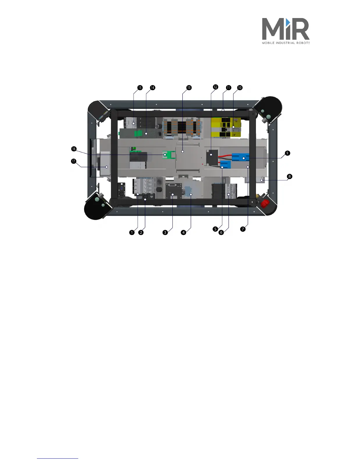
5.4 MiR200™ Inner parts
Figure 5.3. MiR200™ Inner parts
1. Breaker - automatic fuse between battery and
components
10. SICK safety PLC
2. Solid state relay - releases the latching relay (pos.
16) when the robot is shutting down.
11. Optocoupler - emergency stop signal to motor
controller
3. Motor controller - manages the two motor drives 12. Loudspeaker
4. Brake relay - short circuits motor for faster
braking
13. MiR board - interface board for gyroscope,
accelerometer, ultrasound, light, on/off circuit and CAN
bus communication
5. Battery connector for extra battery 14. 24 V power supply - secures stable voltage for PC and
PLC
6. Redundant power for motor controller relays
(controlled by SICK)
15. Latching relay - activates the 24V power supply
turning on the robot
7. CAN bus connection for Battery Management
System, logging data e.g. no of charge cycles.
See MiR Robot Interface 2.0 reference guide
16. Transient protection - provides circuit protection for
the power supplies by absorbing voltage spikes from
battery or top mounted applications
8. Router - local network, 2.4 and 5 GHz 17. NUC PC
9. Battery with connector - main power to the robot


 To Next Page