11
3.0 FX-400 Overview
This chapter lists all the possible components of an FX-400 fire alarm control system.
3.1 FX-400 Fire Alarm Control Panel
The FX-400 Fire Alarm Control Panel has the following features:
• Main Board, Power Supply and Backbox.
• Main Display with 4 x 20 LCD display.
• One Class A, Class X, or Class B SLC analog loop.
• Four Power Limited Class B or Class A NAC circuits (max 1.5 Amps each - 5.0 Amps
total).
• Supports up to 240 MGC MIX-4000 Series addressable devices.
• Dedicated common alarm, supervisory, trouble, and auxiliary alarm relays.
• Additional outputs include connections for a RTI remote trouble indicator, PR-300
Reverse Polarity Module, an RS-485 bus for connection of up to seven RAX-LCD-LITE,
RAM-3318-LCDs, SRM-312s and RA-1000 Series annunciators.
• Auxiliary power is available in the form of 24V FWR unfiltered and unsupervised, 24VDC
filtered and regulated, and resettable auxiliary power supply.
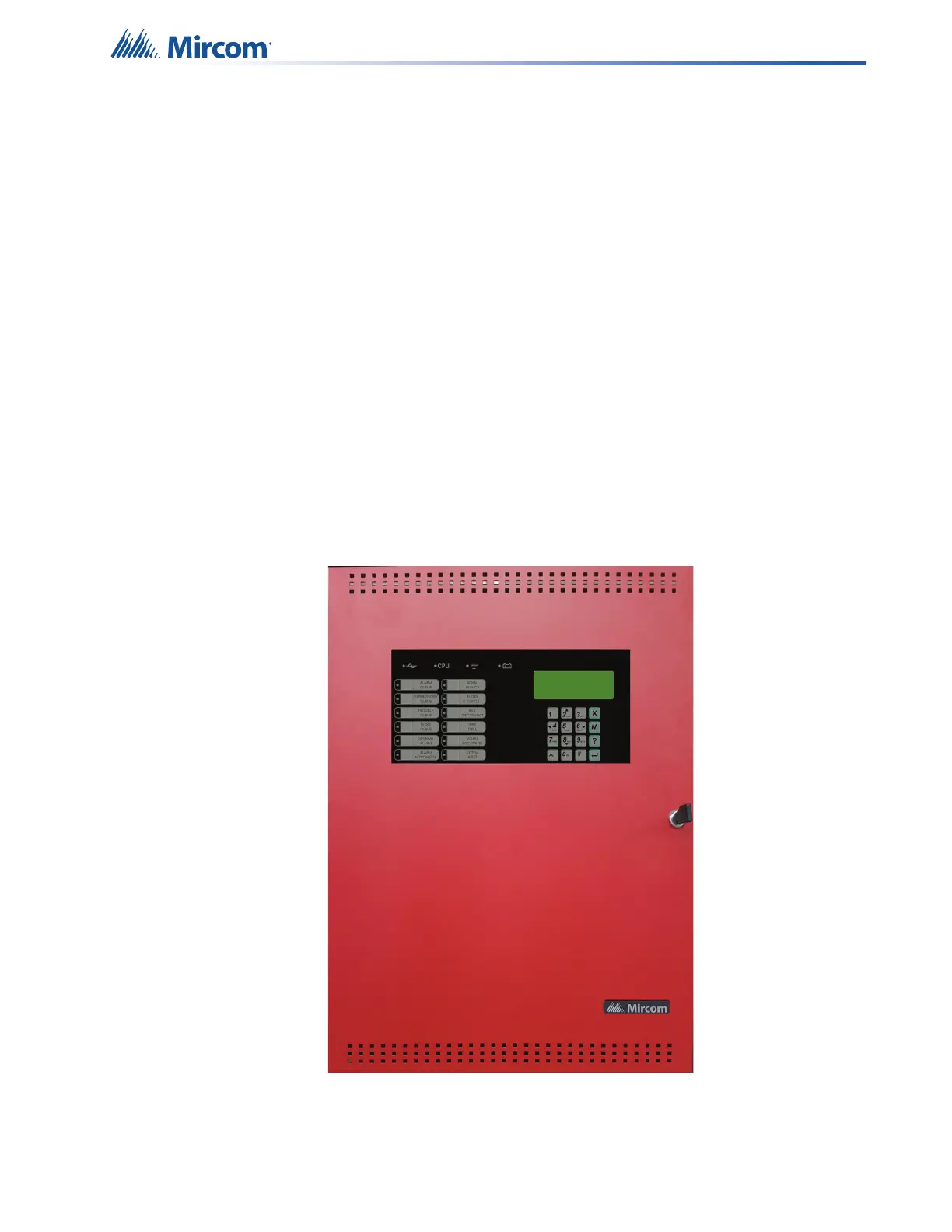
Figure 1 Model FX-400 Single Loop (SLC) Fire Alarm Control Panel