22
The Trouble Transmit signal to the PR-300 can be programmed to delay AC power fail 0, 1, 2,
or 3 hours if this is the only system trouble.
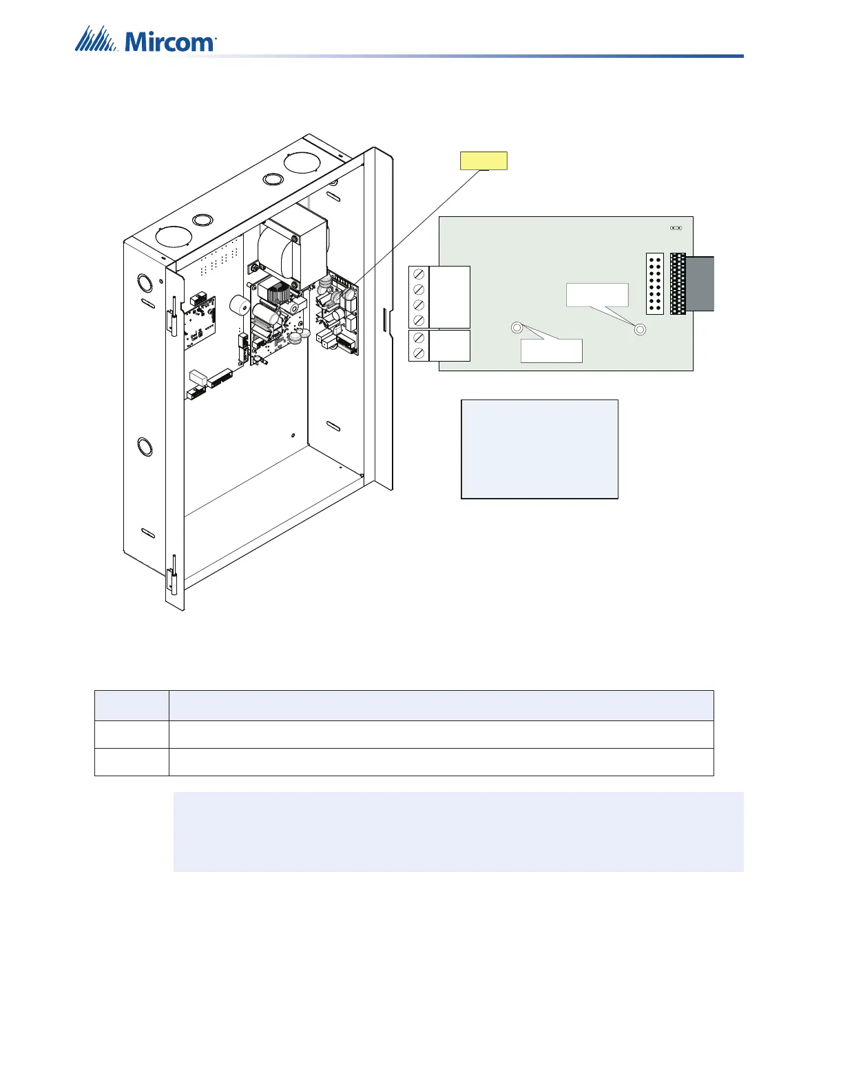
Figure 6 Installing the PR-300 Polarity Reversal and City Tie Module
Table 5 PR-300 Polarity Reversal and City Tie Module Connectors and Jumpers
Item Setting
P1 Connect cable to P8 on the Main Board of the FX-400
JW4 Not used. Keep jumper intact.
Note: If using a PR-300 remember to remove JW7 on the main board. For the location
of JW7 on the main board see Figure 3.
POLARITY
REVERSAL
ALARM
POLARITY
REVERSAL
SUPV
CITY
TIE
+ | - + | - + | -
JW4
P1P2
Mounting hole for
#6-32 screws
Mounting hole for
#6-32 screws
Reverse polarity and city
tie module PR-300.
Mounts on the right hand
side or the backbox
with two screws provided
PR-300