63
7.5.3 Connecting to a NAPCO Starlink SLE-LTEV or SLE-LTEA Interface Device
outside Canada
For information on Compatible Receivers see Appendix A - Compatible Receivers.
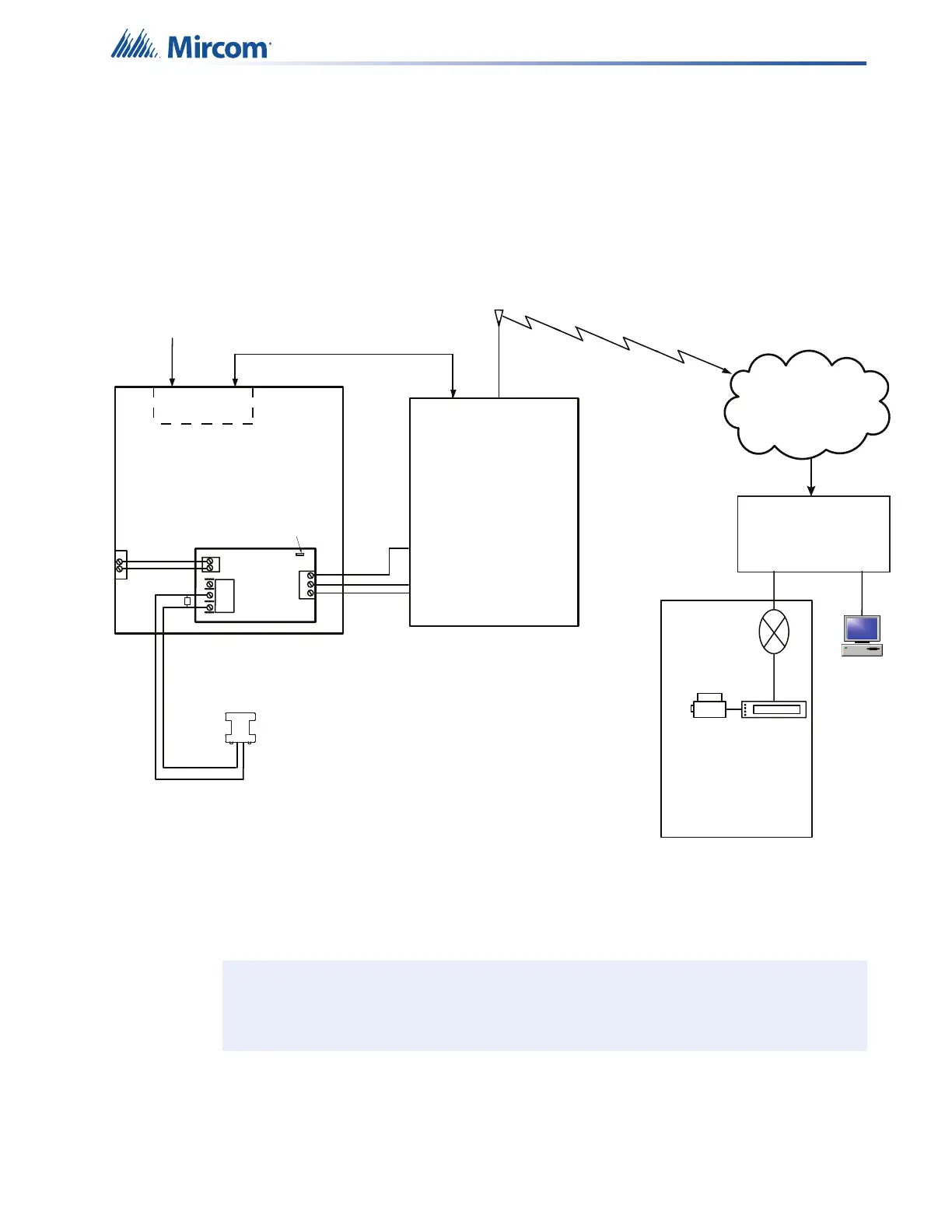
A typical connection is shown in Figure 21. The SLE-LTEV or SLE-LTEA is powered
separately from the PCS-100. The PCS-100 Passive Communications Interface Board (sold
separately) is also required.
Figure 21 Connecting an FX-400 FACP to a SLE-LTEV or SLE-LTEA Interface Device
outside Canada
Note: The NAPCO Starlink interface device SLE-LTEV or SLE-LTEA is required if the
installation requires UL864 10th edition certification.
Telephone
Line A
Connection
E
O
L
Line 2
CO
Line 1
CO
PCS-100
P
OW
E
R
2
4
V
G
N
D
P
G
M4
G
N
D
1
4V
NC
C
O
M
N
O
T
B
L
R
E
L
AY
J
W
1
AUX SUPPLY
+
-
Cellular
Network
Computer
Printer
SUR-GARD
SYSTEM 5
Internal IP: X.X.X.X
External IP: X.X.X.X
SG-Systems
Console 2.1
Default Gateway: X.X.X.X
Sub-Net Mask:X.X.X.X
Port #: YYYY (UDP)
Router
FX-400
FACP
SLE-LTEV
or SLE-LTEA
NAPCO
Starlink
TRBL
FX-400 - NAPCO STARLINK SLE-LTEV or SLE-LTEA Connection - Typical Diagram
Typical Installation outside Canada
- All units must be installed in the same room
- All extended wiring must be in metallic conduit
- Wiring between FACP and SLE-LTEV or SLE-LTEA: 20 feet max.
Addressable module
configured as NAPCO
Starlink radio trouble
Starlink Network
Operations
Central Monitoring Station (Example)
RING TIP
(12) (13)
V+ (1)
- (2)
RF Data
Jumper JW1 on the
PCS-100 shall be set
between pins 2 and 3
PGM1 (3)