78
11.2 FX-400 System Modules and Annunciator Specifications
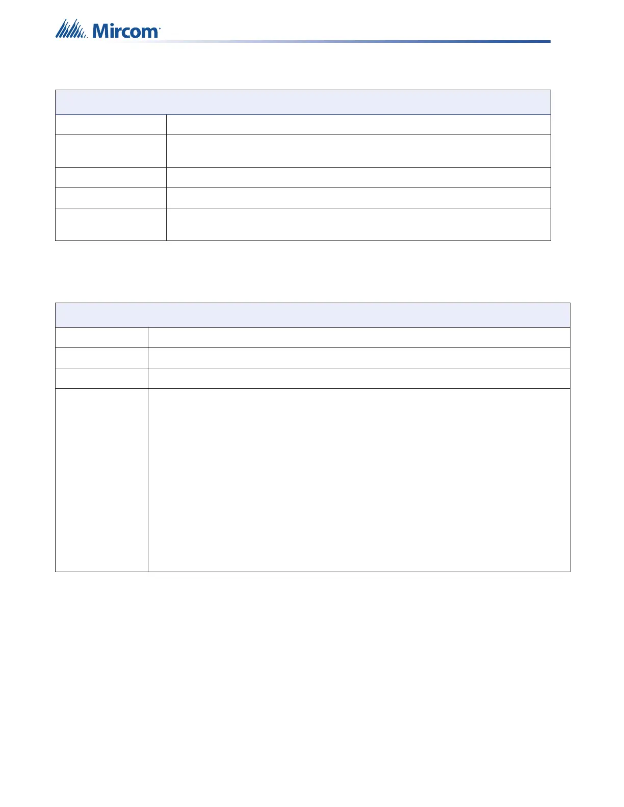
RS-485 port For remote annunciators. Terminals are labelled “RS-485”.
Ground Fault
Impedance
10 K Ohms
Open Circuit Fault 100 K Ohms
Short Circuit Fault 0 Ohms
Applicable
Standards
UL-864 Rev 10, NFPA 70, 72
Table 20 FX-400 System Modules and Annunciator Specifications
FX-400 System Modules and Annunciators
RAM-3318-LCD Remote Annunciator Standby 70mA / alarm 100mA
RAX-LCD-LITE Remote Annunciator Standby 65mA / alarm 80mA
RTI-1 Remote Trouble Indicator Normal standby 0mA / alarm 30mA maximum
PR-300 Polarity Reversal and City Tie Module
City Tie power limited / 24VDC unfiltered / 270mA max / 13.7 and
14.4 Ohms
Polarity Reversal power limited / 24VDC open / 12VDC at 3.5mA / 8mA
max (shorted)
Polarity Reversal Supv.
Terminal
24VDC (normal) / -24VDC (supervisory) / 0V (trouble)
Polarity Reversal Alarm
Terminal
24VDC (normal) / -24VDC (alarm) / 0V (trouble)
Current Consumption standby 50mA / alarm 300mA (city tie in use) / alarm
70mA (city tie not in use)
Table 19 FX-400 Fire Alarm Control Panel Specifications (Continued)
FX-400 Fire Alarm Control Panel