24
5.1.2 Device LEDs
• Polling the devices on the loop causes the device LED to flash normally.
• All device LEDs can be suppressed via the configurator. Suppressing the device LEDs
causes sounder or relay bases to not operate. For an unconfigured device, the LED will
be steadily red. For a device with a built-in isolator, the LED will be steadily yellow if the
isolator is activated.
• Activating devices on the loop (alarm for an input device, active for an output device)
illuminates the device LED steadily red.
• The maximum number of active MGC addressable devices with their LED illuminated
steadily red is 40 for the SLC loop.
5.1.3 Alarm Conditions
Alarm conditions are determined by interrupt which uses thresholds for alarm conditions
stored in the device.
MGC detectors (MIX-4000 series) send an interrupt request to the panel, indicating the Alarm
condition. The system is polling the interrupt group to determine the devices in Alarm. The
Alarm conditions are confirmed by device status flag and comparing reported value against
the threshold.
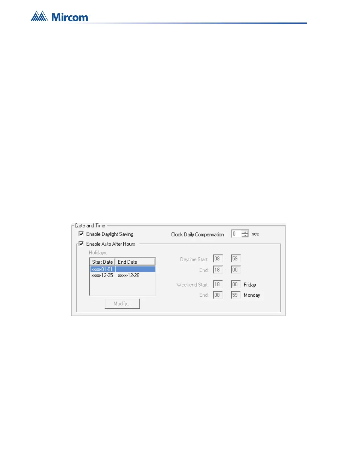
Devices can be individually configured with 2 separate thresholds, “day time” and one “night
time” or after hours operation; i.e. a device may be configured to a low sensitivity for “day time”
and high sensitivity at “night time”. The day time threshold will be used unless the after hours
operation is active. To configure threshold settings, Enable Auto After Hours must be selected
in the configurator.
Figure 7 MGC-3000 Configurator Date and Time Settings
The panel can provide up to 280mA of current to the devices on the loop at normal standby.
For device currents see Appendix E - Battery Calculations on page 79.
For further information refer to the device Installation Instructions and other documentation
provided with the addressable devices, bases, and isolators.
5.1.4 Drift Compensation
Drift Compensation is built into MGC addressable devices, and is not performed by the panel.
Drift Compensation automatically adjusts for gradually increasing effects of dust and other
accumulations of dirt in the detectors. It will adjust the thresholds to compensate for a detector
going dirty according to the gradual change in the normal clean air value received. When it can
no longer compensate for an increasingly dirty detector, a dirty detector trouble is indicated for
that device.