21
See the following diagrams for adder module installation locations. For Jumper or DIP Switch
settings refer to Table 3 and for Wiring Specifications see 7.1 Wiring Tables.
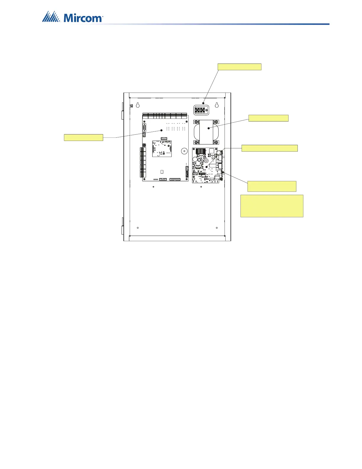
Figure 5 Main Board with all Modules Installed
4.4.1 Installing the PR-300 Polarity Reversal and City Tie Module
Mount the PR-300 as shown in Figure 6.
The Alarm Transmit signal to the PR-300 can be programmed to turn OFF when signal silence
is active. This allows the City Tie Box to be manually reset. On subsequent alarms the
silenceable signals will resound and the City Tie Box will be retriggered.
MD-819 Power Supply Board
PR-300 Polarity Reversal
nd City Tie Module
FX-400 Main Board
TR-061Transformer
Barrier Terminal Block
Note:
The PCS-100 mounts in the same
position as the PR-300. Only one
module may be used.
PR-300 or PCS-100 mounts
on the right-hand side
inside the backbox