34
Ensure that the address DIP switch on each annunciator is set to the same value set in the
configurator. Only the first three (3) DIP switches are used for address configuration.
5.8.1 Supervision of annunciators
• The communications with each annunciator is constantly supervised by the panel and
the annunciator.
• If communications fails, the panel will activate the common trouble sequence. The
number of annunciators is set during panel configuration.
• If there is a mismatch in the total number of annunciators the panel will generate
communications trouble.
• The panel trouble is non-latching: when the correct number of annunciators is detected
the troubles will clear.
5.8.2 RAX-LCD-LITE Shared Display Annunciator
• The RAX-LCD-LITE is equipped with a large 4 line x 20 character backlit alphanumeric
LCD display which uses a simple menu system complete with a directional key pad and
switches for Enter, Menu, Cancel and Info.
• Contains a local alert buzzer.
• Under normal operation the alert buzzer is controlled by the system and operates in an
identical manner as the one in the main panel.
• If communication fails the buzzer is processed locally.
5.8.3 RAM-3318-LCD Shared Display Annunciator
• The RAM-3318-LCD operates identically to the main LCD FACP display.
• Contains a local alert buzzer.
• Under normal operation the alert buzzer is controlled by the system and operates in an
identical manner as the one in the main panel.
• If communication fails the buzzer is processed locally.
5.8.4 Conventional Annunciators
The FX-400 System is designed to interface with the RA-1000 series of conventional LED
annunciators. The LEDs may be configured to zone status indicators. Each conventional
annunciator contains a local alert buzzer. Under normal operation the alert buzzer is controlled
by the system and operates in an identical manner as the one in the main panel. If
communication fails it is processed locally.
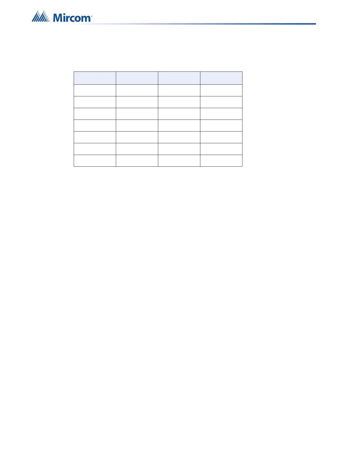
Table 9 Annunciator Address DIP Switch Settings
Address SW1-1 SW1-2 SW1-3
1 ON OFF OFF
2 OFF ON OFF
3 ON ON OFF
4 OFF OFF ON
5 ON OFF ON
6 OFF ON ON
7 ON ON ON