77
11.0 Appendix D - Specifications
11.1 FX-400 Fire Alarm Control Panel
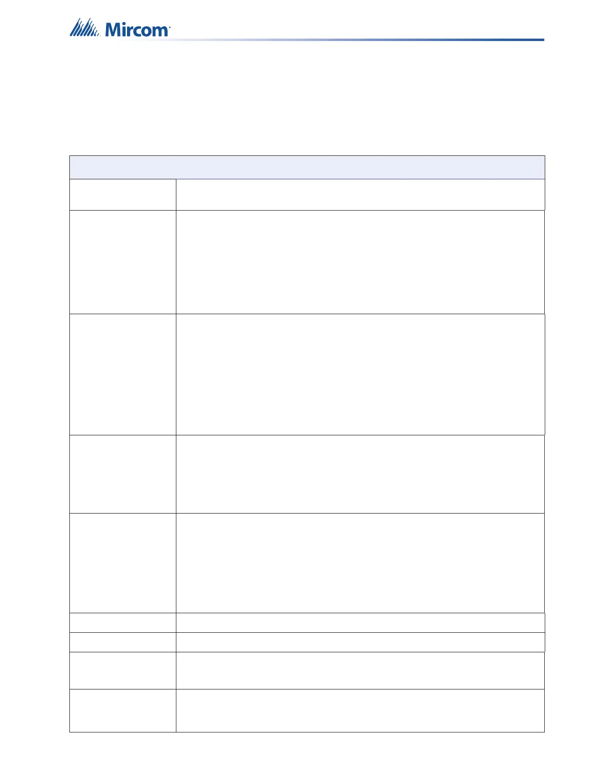
Table 19 FX-400 Fire Alarm Control Panel Specifications
FX-400 Fire Alarm Control Panel
General Digital signal processor based design, fully configurable from LCD display with
optional password protection.
Electrical ratings AC line voltage 120VAC 60Hz/240VAC 50Hz, 10A slow blow mirco in-line
fuse (not field replaceable)
Power supply
rating
29VAC 6A maximum (secondary of transformer)
120VAC 60Hz 1.81 Amp (maximum primary of transformer)
240VAC 50Hz 0.98 Amp (maximum primary of transformer)
Total load not to exceed 5A @ 24VDC
Battery Type 24VDC Gel Cell/Sealed lead acid – 10AH to 24AH
Charging capability 10AH to 24AH
Charging current 1.575A maximum
Protection 10A on-board slow blow micro fuse built (not field
replaceable)
Standby current
rating at full load
0.7A
Addressable loop MGC Protocol SLC loop with 240 MGC addressable devices. Maximum loop
resistance depends on number of devices and device type. For a complete list of
compatible devices see LT-1023 Compatible Devices Guide.
Power Limited / 24V DC / 350mA alarm maximum / 0.5 μF
Power Limited / 24V DC / 280mA normal standby maximum / 0.5 μF
NAC Circuits 4 supervised Class B NAC circuits, configured as strobes or audibles. Terminals
are labelled as “NAC 1”, “NAC 2”, “NAC 3” and “NAC 4”.
Rating Power limited / Regulated 24V FWR / 1.5A @ 49C per
circuit
Max power allowed Total 5.0A
1.5A per circuit
Aux supply 1 Power limited / 24VDC regulated / 500mA max
Aux supply 2 Power limited / 24VDC regulated / 300mA max. Use this supply to power MIX-4042
Unfiltered supply Power limited / 24V FWR special application / 1.7A max @ 49C
List of Compatible Devices: RAM-1032TZDS, RAM-3318-LCD, RAX-LCD-LITE
Auxiliary relays Common Alarm/
Supv./Trouble/
Auxiliary Alarm
Must be connected to a listed power limited source
28VDC/1A max