46
SLC Integration - QX-mini and FX-3500 - Two Stage
7.5 Configuration Steps
7.5.1 FX-3500 Configuration
1. Open FX-3500 configurator.
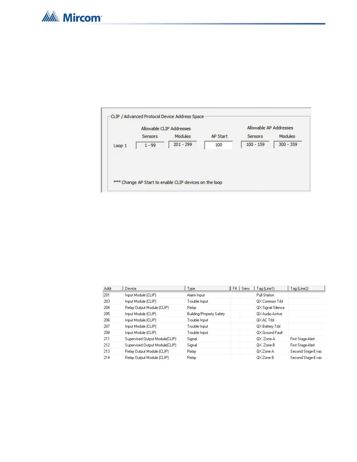
2. Create a new job or open an existing job. Ensure to change “AP Start” to enable CLIP
devices on the loop as QX-mini reporting points will be configured as CLIP devices. “AP
Start” number may vary based on different applications.
Figure 68 CLIP / Advanced Protocol Device Address Space
Note: QX-mini reporting points are configurable in CLIP mode only. It is
important to change AP Start to enable CLIP devices on the loop.
3. Click on the loop that has been wired to SLC terminal on QX-mini Master. Ensure there
is enough space to configure virtual devices on that loop.
4. Configure the loop as shown in the window below. See section 7.7 on page 51 for details
Note: These devices are integrated in QX-mini as “virtual devices” and do
not need to be physically installed on the loop. The number of “virtual
SLC devices” depends on your configuration – you can use as many
as your job requires.
Figure 69 The addresses may vary depending on each application. Ensure
supervised output modules and relay output modules to activate QX-
mini zones are configured as shown above.
5. Ensure all the addresses are correct and job is validated. Connect to the FX-3500 panel
and send the job.