89
13.0 QAS-2X8 Splitter Configuration -
QX-mini and FX-3500 - Two Stage
13.1 Introduction
The QX-mini is designed to interface with Mircom FACPs over an SLC link where it is seen as
a number of “virtual devices.” This single link allows for zone-by-zone automatic control as well
as specific trouble reporting back to the FACP.
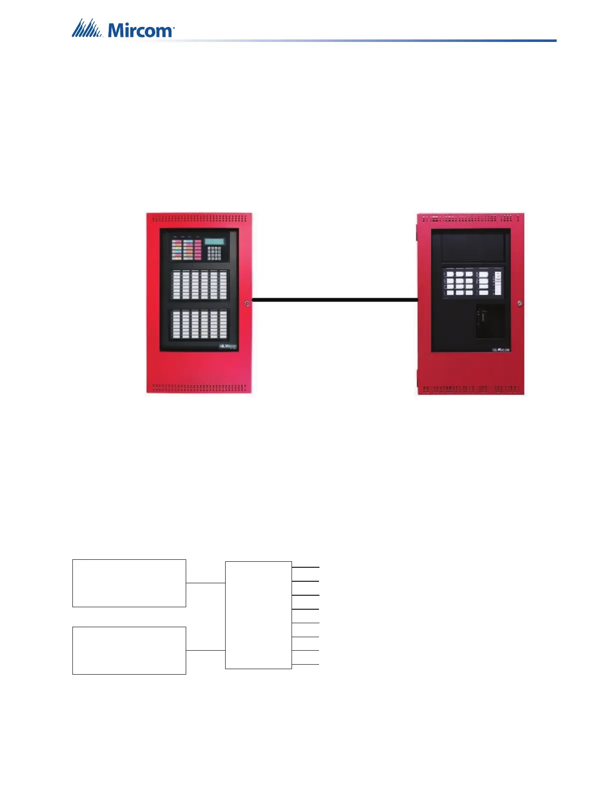
Figure 129 QX-mini and FX-3500
This chapter explains how to program the QAS-2X8 splitter for a modified 2 stage application
with the FX-3500.
Consider an example application with an 8-floor building. If there is an alarm on floor 3, then
floors 2, 3 and 4 are in alarm, and the other floors are in alert. One amplifier provides the alarm
signal, and the other amplifier provides the alert signal. The splitter splits the outputs from the
amplifiers into 8 outputs: 1 output for each floor. In this way, the system provides an alarm
signal to 3 floors (the floor of alarm, and the floor above and below), and an alert signal to the
other floors. Figure 130 shows a conceptual diagram of how the splitter works in this
application. Figure 131 shows how the splitter is wired for this application.
Figure 130 Splitter conceptual diagram
Note:
The QAS-2X8 works with QX-mini configuration software version
2.2.7 and above.
Secondary Amplier
Output 1
Evacuation
Master Amplier
Output 1
Alert
Splitter
Output 8
Output 7
Output 6
Output 5
Output 4
Output 3
Output 2
Output 1
Each splitter output can play
audio from the Master Amplier
or the Secondary Amplier,
or the splitter output can be o