SLC Integration - QX-mini and FleX-Net™ - Single Stage
29
5.3 Configuration Steps
5.3.1 FleX-Net™ Configuration
1. Open FleX-Net™ configurator.
2. Create a new job or open an existing job.
3. Click on the loop that has been wired to SLC terminal on QX-mini Master. Ensure there
is enough space for at least seven devices on that loop.
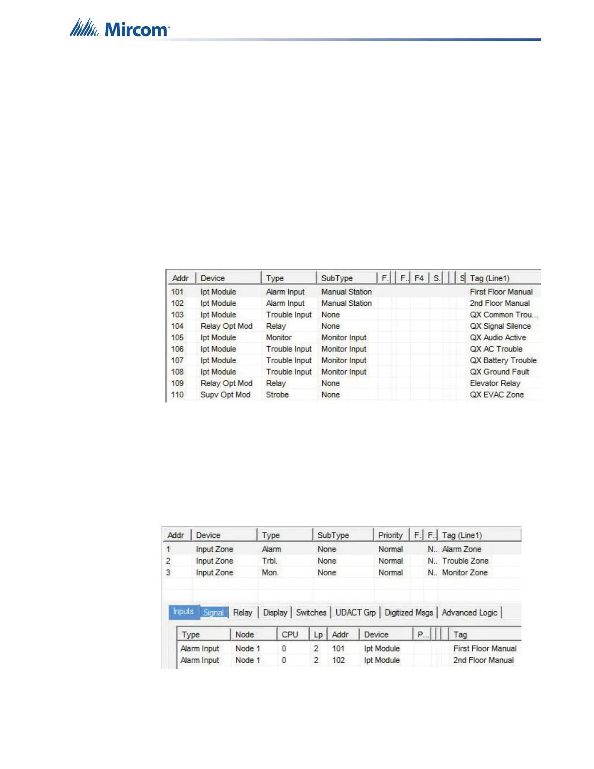
4. Configure the loop as shown in the window below. See section 5.4 on page 34 for
details.
Note: These devices are integrated in QX-mini as “virtual devices” and do
not need to be physically installed on the loop. The number of “virtual
SLC devices” depends on your configuration – you can use as many
as your job requires.
Figure 43 The addresses may vary depending on each application. Ensure
supervised output modules to activate QX-mini zones are configured
after reporting features. Further explanation about this configuration
can be found in section 5.4 on page 34.
5. Create three input zones: Alarm, Trouble, and Monitor.
6. Correlate “Alarm” zone to supervised output modules dedicated for QX-mini zone
activation. Additionally, correlate all the alarm activating devices to this input zone. See
5.4 on page 34 for details.
Figure 44 Alarm zone correlations