3 - 4
3 DESIGN
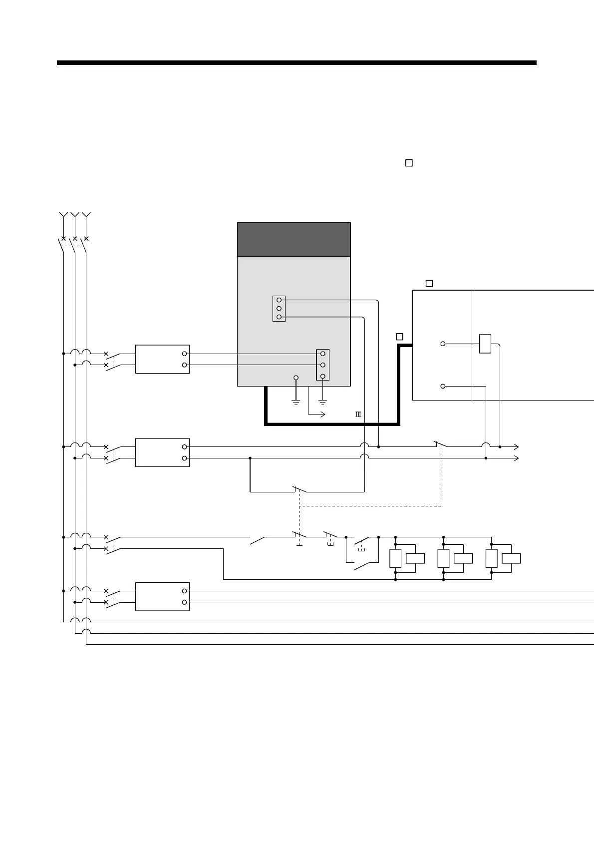
3.2 External Circuit Design
As to the ways to design the external circuits of the Motion system, this section
describes the method and instructions for designing the power supply circuits and
safety circuits, etc. (Example: Q170MSCPU and MR-J4-
B use)
(1) Sample system circuit design for Motion CPU area
(Note-2)
Servo normal
output
(Servo normal: ON,
Alarm: OFF)
RA1
SK
MC3
SK
MC1 to 3
RA1
Ready
ON
Operation
OFF
(Note-6)
Surge suppresser
EMG
MC2
(Note-6)
MC1
SK
(Note-6)
QC B
Output module
QY10
COM
PYm
Power supply for
electromagnetic brake
CP3
CP4
+24V
24G
24VDC
Power
supply
Power supply for I/O
+24V
24G
24VDC
Power
supply
CP2
MCCB1
RST
3-phase
200 to 230VAC
Power supply for Q170MSCPU
+24V
24G
24VDC
Power
supply
CP1
Emergency Stop
EMG
+24V
24G
EMG
SSCNET /H
Q170MSCPU
+24V
24G
FG
Forced stop
(Note-1)
EMI
EMI.COM
FG
Q5 B
 Loading...


