2-12 Installation
2Unpacking to installation
2.2.4 Connecting the power cable and grounding cable
The following shows how to connect the power cables and grounding cables.
(1) Connecting the power cable (CR750 controller)
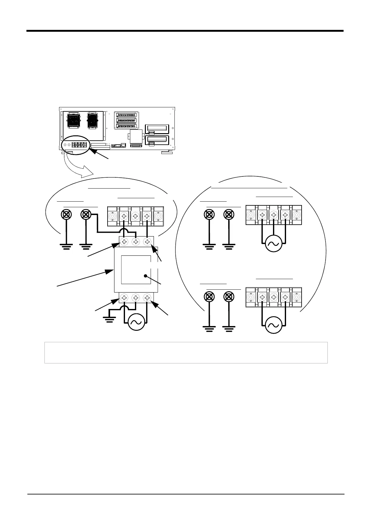
Fig. 2-6 : Connecting the power cable and grounding cable
1) Prepare the power cable (AWG#14 (2mm
2
) or more).
2) Loosen the two screws fixing the terminal cover, and remove the cover.
3) Confirm that the primary power matches the specifications.
4) Confirm that the primary power is OFF and that the controller power switch is OFF.
5) Connects the cable for the primary power supply connection to the ACIN terminal block of the controller.
When the terminal for single phase is attached, connect the primary power supply to L1 and L2 terminal.
When the terminal for single phase/ three phase is attached, connect the primary power supply to L1, L2
and L3 terminal when using the three phase primary power supply, and connect the primary power supply
to L1 and L3 terminal when using the single phase primary power supply.
6) Install the power terminal cover as before.
This completes the connection of the power and grounding cables.
Grounding
ACIN terminal
L1
Single phase primary power supply
N/L2
terminal (PE)
ACIN terminal
L1 L3L2
Three phase primary power supply
Grounding
terminal (PE)
ACIN terminal
L1 L3L2
Single phase primary power supply
Grounding
terminal (PE)
ACIN terminal
Remove the cover
Note) When fixing the power cable to the ACIN terminal block with screws, be sure to hold the crimp terminal with your
hand to ensure that it does not rotate while fastening screws.
The dividers between terminals of the ACIN terminal block are fragile and may break if pressed.
Note 1) Fix the primary power cable to the terminal with the
screw.
Screw size: M4
Solderless terminal: φ8 or less
Recommendation: 2-M4
(JAPANESE SOLDERLESS TERMINALS
CO.,LTD.)
Wire size: AWG #14(2mm
2
)/ for M4 screw.
Note 2) Non CE specification: L2
CE specification: N
Note 3) In the CE specification, as shown in the figure, con
-
nects the noise filter (SUP-EL20-ER6) of attach
-
ment between ACIN terminal blocks and primary
power supply.
Note 2)
<4> LINE/LOAD
<3> LINE/LOAD
<1> LINE/LOAD
<2> LINE/LOAD
Noise filter (attachment)
Type: SUP-EL20-ER
Label
Note 3)
For single phase
For single phase/three phase
Note 1)
Note 1)
 Loading...


