4-42 Handling the controller
4Basic operations
(2) CR751 controller
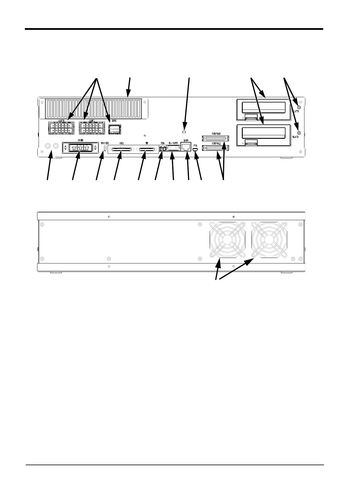
Fig.4-2 : Names of controller parts (CR751)
<1> ACIN connector.......................................The connector for AC power source (1-phase, AC200V) input (a socket
housing and a terminal are attached)
<2> PE terminal ................................................The screw for grounding of the cable. (M4 screw x 2 place)
<3> POWER lamp.............................................Lamp of control power source
<4> Machine cable connector (motor power)
AMP1, AMP2: Motor power, BRK: Motor brake
<5> Machine cable connector (motor signal)
CN2: Motor signal
<6>T/B connection connector (TB) ........This is a dedicated connector for connecting the R33TB. When not using T/
B, connect the attached dummy plug.
<7>Filter cover..................................................There is an air filter and buttery inside this cover.
<8>CNUSR connector....................................The connector for input/ output connection dedicated for robot.
(CNUSR1、 CNUSR2) (a plug connector attached)
<9>Grounding terminal...................................The grounding terminal for connecting cables of option card. (M3 screw x 2
places)
<10>Power supply charge lamp (CRARGE)
The lamp is to ensure safe timing (prevent electric shocks) when removing
the cover (users are not normally required to remove the cover).
This lamp is illuminated (red) when electrical energy accumulates on the
controller’s power supply circuit board due to the robot’s servo being ON.
After turning the control power OFF and allowing a few minutes to pass,
the lamp will go out.
<2> <1> <3>
<4> <7> <15> <9>
<5> <6> <14> <13> <12><11> <8>
<10>
Controller (Front side)
Exhaust
Controller (Rear side)
 Loading...


