2Unpacking to installation
Installation 2-13
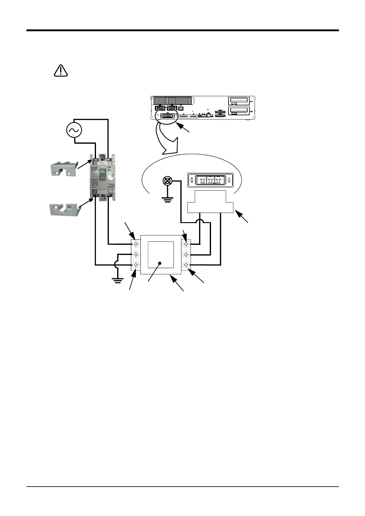
(2) Connecting the power cable (CR751 controller)
Fig. 2-7 : Connecting the power cable and grounding cable
1) Please prepare the following: Leakage current breaker (with terminal cover), cable for connecting the
primary power supply, cable for connecting the secondary power supply (both AWG #14 (2mm
2
)), cables to
ground the primary power supply (AWG #12 (3.5mm
2
or above).
2) Confirm that the primary power matches the specifications.
3) Confirm that the primary power is OFF and that the earth leakage breaker power switch is OFF.
4) Connect the secondary power cable to secondary terminal (lower terminal) of earth leakage breaker.
Connect the opposite side of this cable with "1" and "3" of the ACIN connector attached. Recommends
connection by the Solderless terminal.
5) Connect this connector to the ACIN connector on the controller.
6) Connect the grounding cable to the PE terminal. (M4 screw)
7) Connect the primary power cable to the primary side terminal (upper terminal) of the earth leakage breaker.
This completes the connection of the power and grounding cables.
PE terminal
Earth leakage
braker (NV)
Cover
Cover
Grounding screw
Controller
Connector
AC200V
Primary
Secondary
Use an earth leakage breaker (customer preparation) in the primary power supply
circuit of the controller to prevent short circuit.
ACIN connector
Note1)
Note 1) The earth leakage breaker is the customer preparation.
Recommendation: NV30FAU-2P-10A-AC100-240V-30mA, (Cover: TCS-05FA2)
Note 2) In the CE specification, as shown in the figure, connects the noise filter (SUP-EL20-ER6) of attachment between
ACIN terminal blocks and primary power supply.
Included ACIN connector
Attach to pin numbers 1 to 3
* Crimping swage is recommended
for connecting
(soldering is also possible)
Recommendation compression tools:
234171-1(Tyco Electronics)
Controller
<4> LINE/LOAD
<3> LINE/LOAD
<1> LINE/LOAD
<2> LINE/LOAD
Noise filter (attachment)
Type: SUP-EL20-ER
Label
Note 2)
 Loading...


