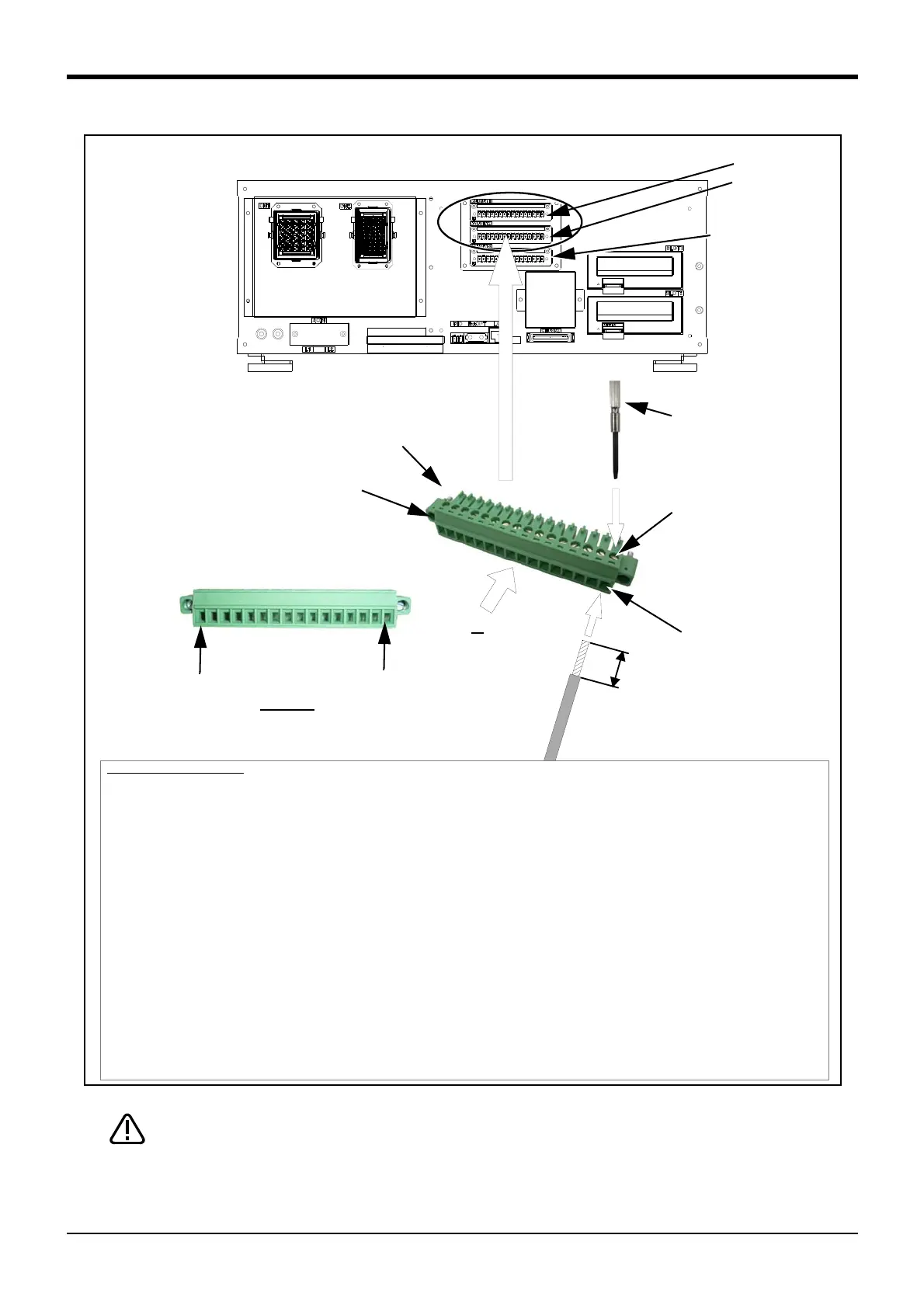
Fig. 2-10 : Method of wiring for external emergency stop connection (CR750 controller (CNUSR11/12))
CNUSR11 or CNUSR12. Be careful not to connect to CNUSR13 as the robot will not
operate properly.
<CR750 controller>
CNUSR11/12 connector
CNUSR11
CNUSR12
Driver
*Recommendation driver
size: 2.5mm.
Cable fixing screw
Cable insert point
7mm
A
View A
16
1
Connector fixing screw
(Two places)
Pin number of connector
Connecting cable
(AWG #26-16 (0.14mm-1.5mm
2
))
Connection procedure
Insert the connection cable into the appropriate pin of the user wiring connector that accompanies the product. Fix
it securely with a screw and connect the connector to the CNUSR11/CNUSR12 connector at the back of the
controller.
Please use an AWG #26 to 16 (0.14 to 1.5mm
2
) connector cable.
1) Prepare the user wiring connector that accompanies the product.
2) Loosen the cable fixing screw at the point where the cable is to be inserted. Please use a screwdriver head
with a width of 2.5mm to loosen the screw.
3) Peel the insulation of the connecting cable to 7mm, and insert it into the cable slot of the corresponding con
-
nector.
4) Be sure to fix the inserted cable securely by fastening a cable fixing screw.
(tightening torque of 0.22 to 0.25Nm)
5) After the necessary cables save been fixed, connect the connector to the connector (CNUSR11/12) that cor
-
responds with the controller. Connect so that the cable fixing screw is comes on top, and make sure to fix
securely by fastening connector fixing screws in two places. A screwdriver head with a width of 2.5mm should
be used to fix screws (tightening torque of 0.22 to 0.25Nm).
This concludes the connection procedure.
Connector for user wiring
Reference: CNUSR13
(Connect the encoder,
when using the
tracking function)
 Loading...


