4Basic operations
Handling the T/B 4-45
(2) Installing the T/B (CR751 controller)
Explain the installation method of T/B below.
1) Check that the POWER (power supply) switch of the robot controller is OFF.
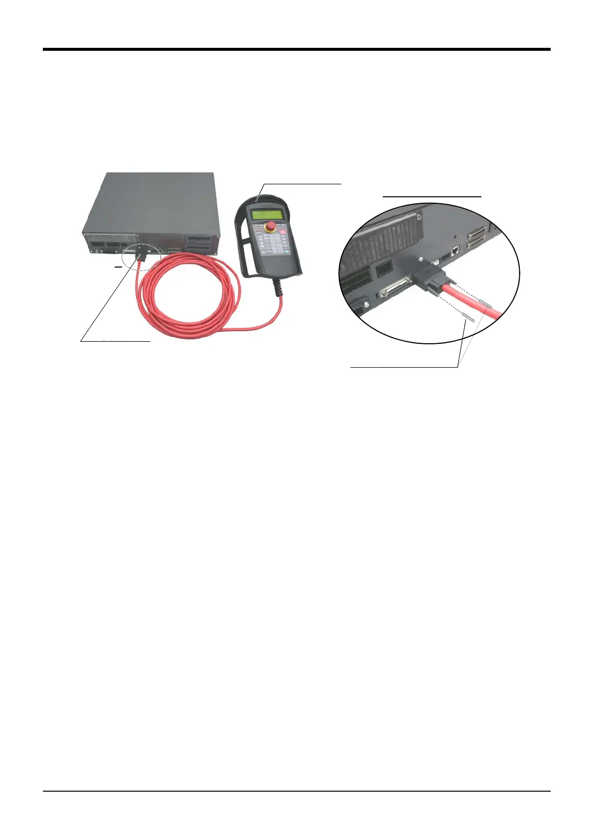
2) Connect the T/B connector to the controller’s T/B connector. Make sure to fix it securely by fastening the
hand locks (in 2 places), as shown in Fig. 4-4.
Fig. 4-4 : Installing and removing the T/B (CR751 controller)
The installation of T/B is finished.
(3) Removing the T/B (CR750 controller)
Explain the removing method of T/B below.
1) Check that the POWER (power supply) switch of the robot controller is OFF.
2) Raise up the lock lever in the connector upper part , and pull up the connector.
Please install the dummy connector, if you use the robot, without connecting T/B.
The removing of T/B is finished.
(4) Removing the T/B (CR751 controller)
Explain the removing method of T/B below.
1) Check that the POWER (power supply) switch of the robot controller is OFF.
2) Loosen the handle locks (two places) of a connector, and pull up the connector.
Please install the dummy connector, if you use the robot, without connecting T/B.
The removing of T/B is finished.
A部
ティーチングボックス
(T/B)
T/B接続用コネクタ
A部詳細
手回しロック(2箇所)
Controller
T/B connector
Teaching pendant
Details of the A section
A
Hand lock (Two places)
 Loading...


